

Optimization of the electromagnetic stirring position at solidification end of 50CrV continuous casting billet
-
摘要: 为标定240 mm×240 mm断面50CrV弹簧钢方坯的凝固末端位置,确定凝固末端电磁搅拌的合理位置,对湘钢方坯连铸机开展射钉试验,结果表明,弹簧钢方坯综合凝固系数为26.8 mm/min1/2,在0.8 m/min和1.0 m/min拉速下,凝固终点位置分别为距弯月面16.2 m和19.8 m处,凝固末端电磁搅拌适宜位置为距弯月面7.18 m和8.84 m处。基于射钉试验建立凝固传热模型,利用模型研究了不同连铸工艺参数下的铸坯凝固特征,据此可对现行连铸参数进行优化与修正,充分发挥凝固末端电磁搅拌作用,减轻中心偏析,改善铸坯质量,研究结果对现场实际具有一定指导意义。Abstract: In order to calibrate the solidified end position of the 50CrV spring steel billet with 240 mm×240 mm section and determine the reasonable position of electromagnetic stirring at the solidification end, the nail shooting experiment was carried out on the Xianggang billet continuous caster. The results showed that the comprehensive solidification coefficient of the spring steel billet was 26.8 mm/min1/2. When the casting speed are at 0.8 m/min and 1.0 m/min, respectively, The end positions of solidification are 16.2 m and 19.8 m from the meniscus surface, respectively, and the suitable positions of electromagnetic stirring at the end of solidification are 7.18 m and 8.84 m from the meniscus surface. Based on the verification of the nail test, the solidification heat transfer model was established, and had been used to studied the solidification characteristics of the casting billet under different continuous casting process parameters. The model predication could be used to optimize and correct the existing continuous casting parameters so that the electromagnetic stirring effect at the solidification end could be fully exerted and the central segregation should be reduced, consequently the quality of the casting billet could be improved.
-
0. 引言
无取向硅钢中析出物的粒径为0.1~1 μm时,会导致最终的磁性能降低[1−4]。分析其原因,是百纳米级夹杂物的存在阻碍了磁畴壁(尺寸为100~900 nm)的正常移动[5−7],使得晶粒不能正常长大[8−10],最终降低了无取向硅钢产品的磁性能[11]。Boc I 等人[7]的研究得到了以下结论:夹杂物粒子在0.005~0.5 μm范围和直径>0.5 μm或者<0.005 μm的粒子分别进行比较,结果得出0.005~0.5 μm粒径对磁性能重要得多。
文献[4]介绍了高牌号硅钢的硫化物和氮化物的析出热力学计算,但是由于高端牌号硅钢本身的保密性,即使不同企业同一牌号硅钢成分之间也并不一致,尤其针对Al、Mn等额外添加的合金元素,此外S和N的含量也体现了各个企业炼钢水平的高低,上述成分之间差距均较大。
为此,笔者以国内某厂的高牌号无取向硅钢50W350中的MnS、Cu2S、AlN和TiN为例,针对具体生产单位的高牌号中硫、氮化物等展开热力学分析,从热力学角度研究了无取向硅钢生产过程中析出物的规律。
1. 热力学计算推导
由于热力学计算获得的是平衡浓度积和温度之间的关系,进而可以得到具体硫、氮化物的析出温度,这对现场理论指导有重要意义。
由于MnS、Cu2S、AlN和TiN随着钢水降温过程中溶解度逐渐发生变化,且固液相之间变化趋势不同,因此当实际溶度积(Q)大于平衡溶度积(K)时,意味着析出物开始析出。钢中的金属M(铝、锰等)与非金属X(氮、硫)残余反应生成MX。在反应过程中平衡常数的计算如式(1)所示。
$$ K\mathrm{_{eq}}=\dfrac{a_{\mathrm{M}\mathrm{X}}}{a_{\mathrm{M}}a_{\mathrm{X}}}=\dfrac{1}{f_{\mathrm{M}}\left[\mathrm{\%}\mathrm{M}\right]f_{\mathrm{X}}\left[\mathrm{\%}\mathrm{X}\right]} $$ (1) 式中, [%M]为金属质量百分含量; [%X]为氮、硫的质量百分数;fM为金属元素活度系数;fX为氮、硫的活度系数。
根据MX反应的$ \Delta {G}^{{\theta }} $数据可得:
$$ \mathrm{l}\mathrm{g}{K}_{\mathrm{e}\mathrm{q}}=-\dfrac{\Delta {G}^{{\theta }}}{2.3RT}=B-\dfrac{A}{T} $$ (2) 式(1)取对数,代入式(2)可得式(3):
$$ \mathrm{lg}\left[\mathrm{\%}\mathrm{M}\right]+\mathrm{lg}\left[\mathrm{\%}\mathrm{X}\right]+\mathrm{l}\mathrm{g}{f}_{\mathrm{M}}+\mathrm{l}\mathrm{g}{f}_{\mathrm{X}}=B-\dfrac{A}{T} $$ (3) 式中,B代表$ \dfrac{\Delta S}{2.3 R} $计算得到的具体数值,其中$ \Delta S $为熵变,R为8.314 J/(mol·K); A代表$ \dfrac{\Delta H}{2.3 R} $计算得到的具体数值,其中$ \Delta H $为焓变。
由于钢中有关MnS、Cu2S、AlN和TiN生成反应的$ \mathrm{l}\mathrm{g}{f}_{\mathrm{M}}、\mathrm{l}\mathrm{g}{f}_{\mathrm{X}} $值对式(3)中B值的影响很小,可以将式(3)转换为式(4)。
$$ \mathrm{lg}\left[\mathrm{\%}\mathrm{M}\right]\left[\mathrm{\%}\mathrm{X}\right]=-\dfrac{\Delta {G}^{\theta }}{2.3RT}=B-\dfrac{A}{T} $$ (4) 经过上述公式的推导,可以获得具体的B和A,此外也可获得平衡溶度积K和实际溶度积Q,如表1所示。
化合物 K Q 相 AlN 6.334- 14069 /T[%Al][%N] 液相 MnS 4.63- 8750 /T[%Mn][%S] 液相 AlN 5.37- 14640 /T[%Al][%N] δ相 AlN 2.27- 10590 /T[%Mn][%S] δ相 Cu2S 26.31- 44791 /T[%Cu]2[%S] 液相+δ相 TiN 5.56- 17025 /T[%Ti][%N] 液相+δ相 当钢水温度降低到两相区时,钢中的溶质元素等元素发生偏析,此时氮、硫的含量及锰、铝元素的含量分别用式(5)(6)计算。
$$ \left[\mathrm{\%}\mathrm{X}\right]=\dfrac{{\left[\mathrm{\%}\mathrm{X}\right]}_{0}}{{f}_{\mathrm{s}}\left({k}_{\mathrm{X}}-1\right)+1} $$ (5) $$ \left[\mathrm{\%}\mathrm{M}\right]={\left[\mathrm{\%}\mathrm{M}\right]}_{0}{(1-{f}_{\mathrm{s}})}^{{k}_{\mathrm{M}}-1} $$ (6) 式中, fs为固相百分率;kM为金属元素M的平衡溶质分配因数;kX为非金属X的平衡溶质分配因数;析出物形成实际的浓度积QMX可表示为[4]:
$$ Q_{\mathrm{MX}}=[\% \mathrm{M}][\% \mathrm{X}]=\frac{[\% \mathrm{M}]_0[\% \mathrm{X}]_0\left(1-f_{\mathrm{s}}\right)^{k_{\mathrm{M}}-1}}{f_{\mathrm{s}}\left(k_{\mathrm{X}}-1\right)+1} $$ (7) 温度T与固相百分率fs的关系如式(8)表示。
$$ {f}_{\mathrm{s}}=\frac{({T}_{\mathrm{F}\mathrm{e}}-{T}_{\mathrm{s}})({T}_{\mathrm{l}}-T)}{({T}_{\mathrm{l}}-{T}_{\mathrm{s}})({T}_{\mathrm{F}\mathrm{e}}-T)} $$ (8) 式中, T为凝固过程中液相温度,K;TFe为纯铁的熔点(1 809 K);TL为液相线温度,K;TS为固相线温度,K。
2. 热力学计算条件
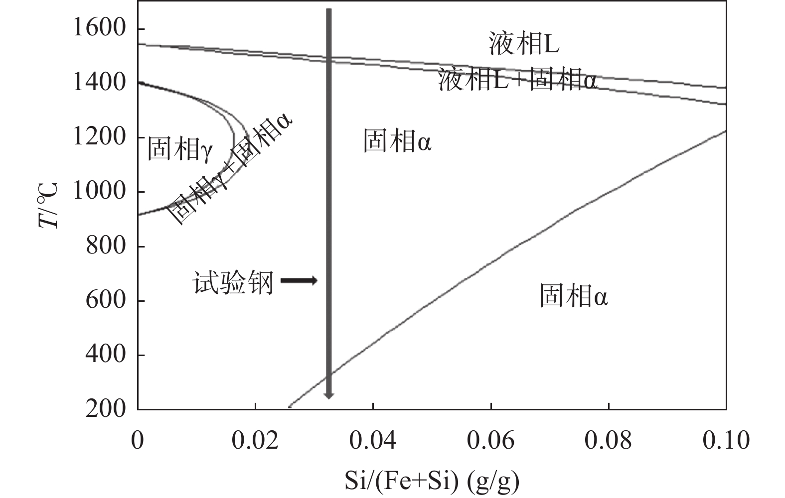
计算钢种为模拟高牌号典型无取向硅钢种50W350,其主要化学成分如表2所示。分别通过FactSage软件Phase Diagram相图计算模块,其在铁硅相图中位置如图1所示,绿色线代表试验钢在相图中的具体位置。表3为各个阶段的平衡溶质分配因数和液相线。
表 2 试验钢的主要化学成分Table 2. Main chemical composition of the tested steel% C Mn Si S P Als N Ti Cu 0.0019 0.32 2.72 0.0023 0.014 0.5016 0.0015 0.0026 0.046  图 1 Fe-Si二元相图 ( FactSage software)Figure 1. Fe-Si binary phase diagram ( FactSage software)
液相线和固相线采用如下公式计算[4]:
$${\begin{split} & {T_{\mathrm{L}}} = 1536 + 273 - \Big\{ [90[\% {\mathrm{C}}] + 6.2[\% {\mathrm{Si}}] + 1.7[\% {\mathrm{Mn}}] + \\ & 28\left[ {\% {\mathrm{P}}} \right] + 40\left[ {\% {\mathrm{S}}} \right] + 2.6[\% {\mathrm{Cu}}] + 2.9[\% {\mathrm{Ni}}] + 1.8[\% {\mathrm{Cr}}] +\\ & 5.1[\% {\mathrm{Al}}]\Big\} \\[-16pt] \end{split}} $$ (9) $$ {\begin{split} &{T_{\mathrm{s}}} = 1536 + 273 - \{ [415.3[\% {\mathrm{C}}] + 12.3[\% {\mathrm{Si}}] +6.8 \\ & [\% {\mathrm{Mn}}] +124.5\left[ {\% P} \right] + 183.9\left[ {\% S} \right] + 1.4[\% {\mathrm{Cu}}] +4.3\\ & [\% {\mathrm{Ni}}] +1.4[\% {\mathrm{Cr}}] + 4.1[\% {\mathrm{Al}}]\}\\[-16pt] \end{split}} $$ (10) 3. 热力学计算结果
3.1 液相计算结果
从表3可以看出,液相线
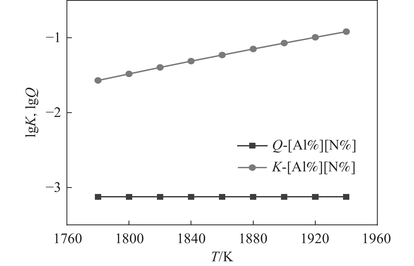
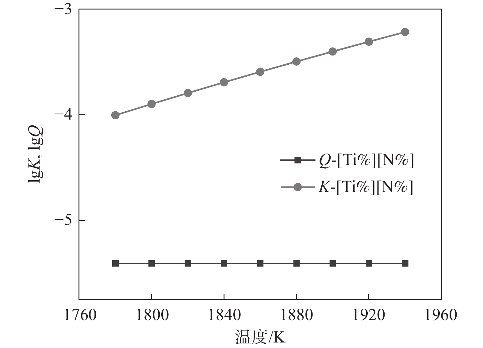
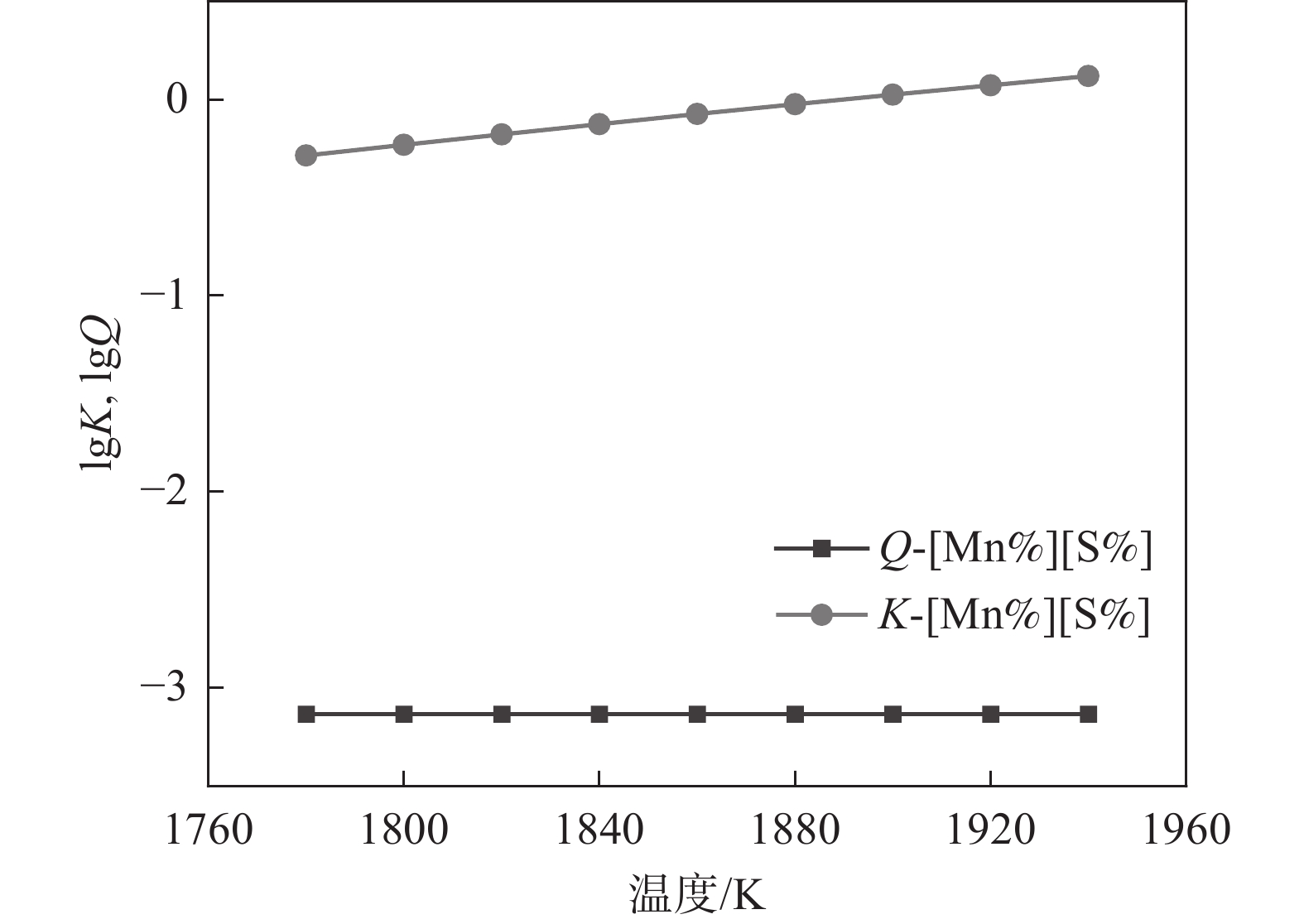
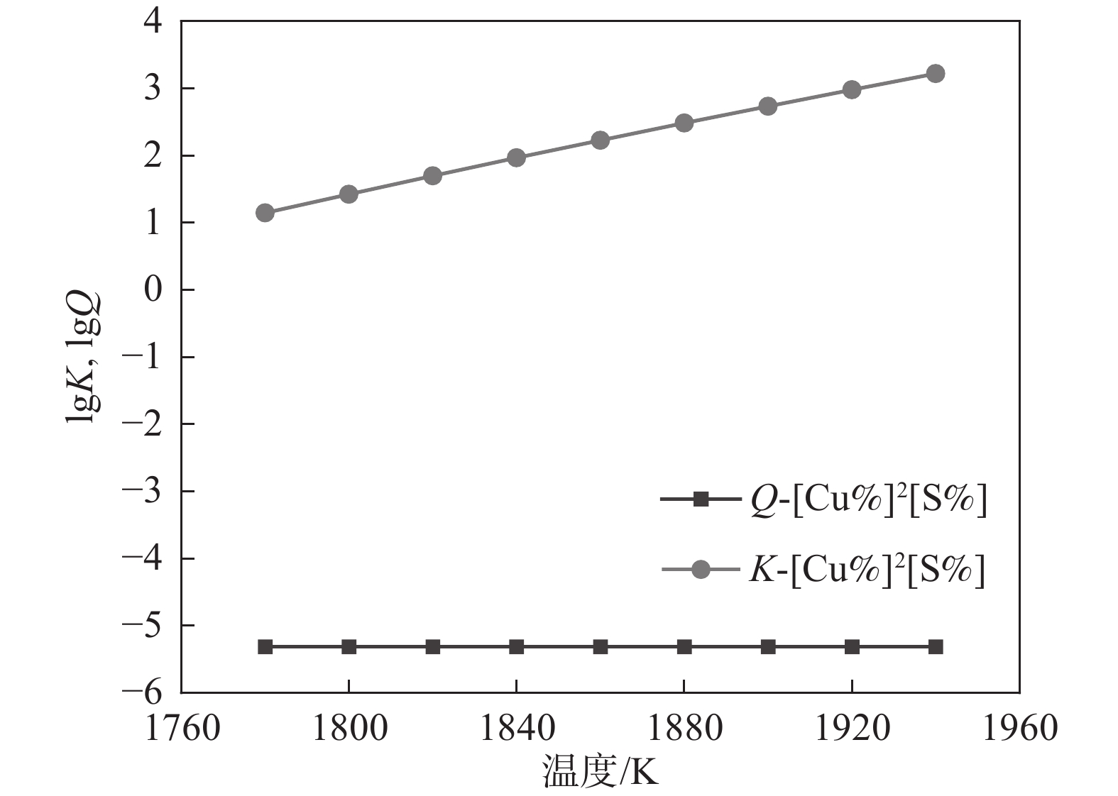
1788 K,因此本小节计算的结果是温度在1788 K以上的部分。将热力学数据代入式(4)得出AlN、TiN、MnS和Cu2S在钢液中的平衡溶度积。图2~5中为平衡溶度积和实际溶度积取对数。从表1可以看出,平衡溶度积与温度T呈现正相关关系,图2~5中曲线K对此可以作出相关解释。钢中温度从液相线1788 K上升到1 940 K,AlN平衡溶度积K的取值范围为−1.57~−0.91,MnS的平衡溶度积K取值在−0.29~0.11;AlN和MnS的Q和K两条曲线均没有交集,且Q值始终小于K,即AlN和MnS都不可能析出。同理对TiN和Cu2S进行相关分析,两者的Q都小于K,都不能析出。3.2 凝固过程分析
50W350牌号无取向硅钢凝固过程中不存在γ相,这一点从图1中可以看出,因此只需要计算L→α和完全α即可。从表3可以看出,固相线温度为
1768 K,液相线温度为1788 K,由于凝固阶段包含固液相温度区间以及完全α阶段, 即L→α阶段,即1768 ~1788 K和固相线温度以下部分完全α阶段,即小于1768 K。3.2.1 L→α阶段
根据溶度积公式计算,将固液相线代入公式(8),得到固相率$ \mathrm{\mathit{f}}_{\mathrm{s}} $,再将固相率代入公式(7),就可以得到实际平衡浓度积Q。图6~9为相关氮化物、硫化物溶度积曲线。
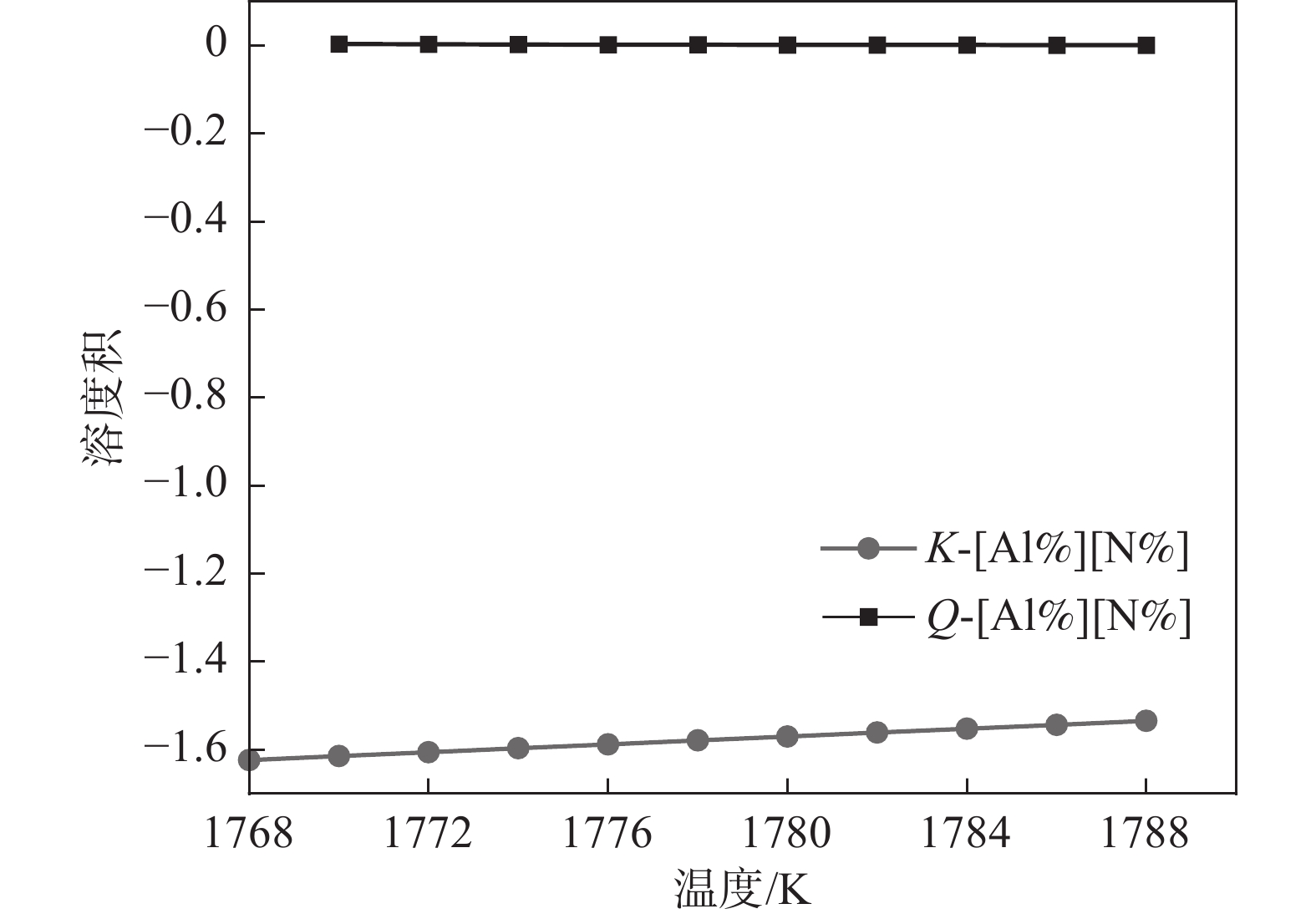
 图 6 凝固过程中AlN析出溶度积关系Figure 6. Relationship of solubility product of AlN precipitation and temperature during solidification process
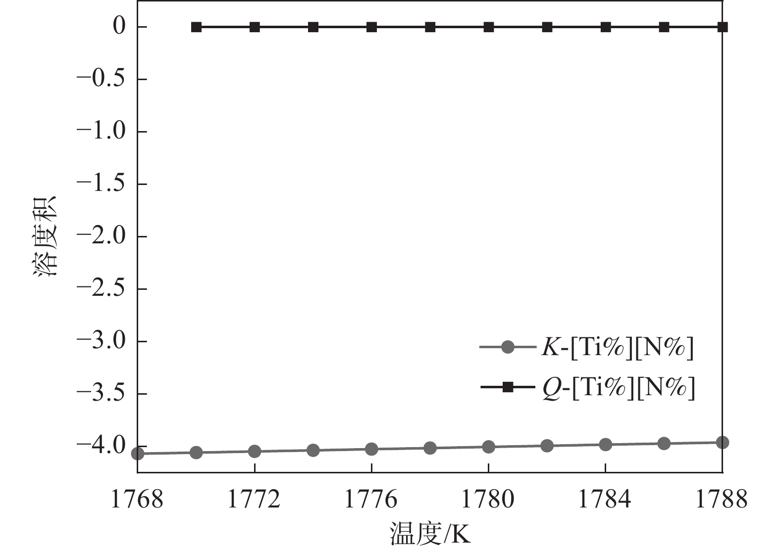
 图 7 凝固过程中TiN析出溶度积关系Figure 7. Relationship of solubility product of TiN precipitation and temperature during solidification process
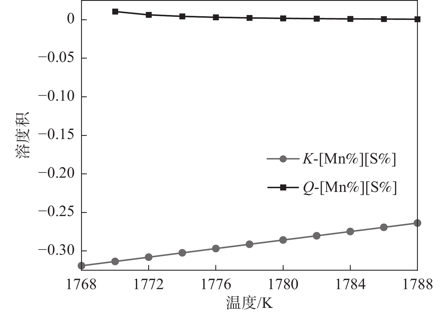
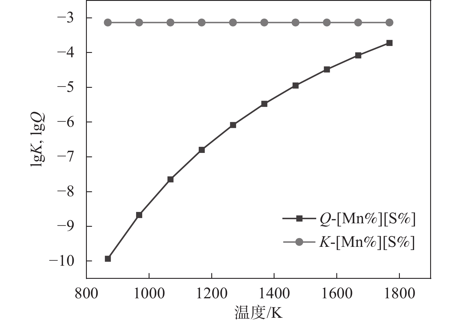
 图 8 凝固过程中MnS析出溶度积关系Figure 8. Relationship of solubility product of MnS precipitation and temperature during solidification process
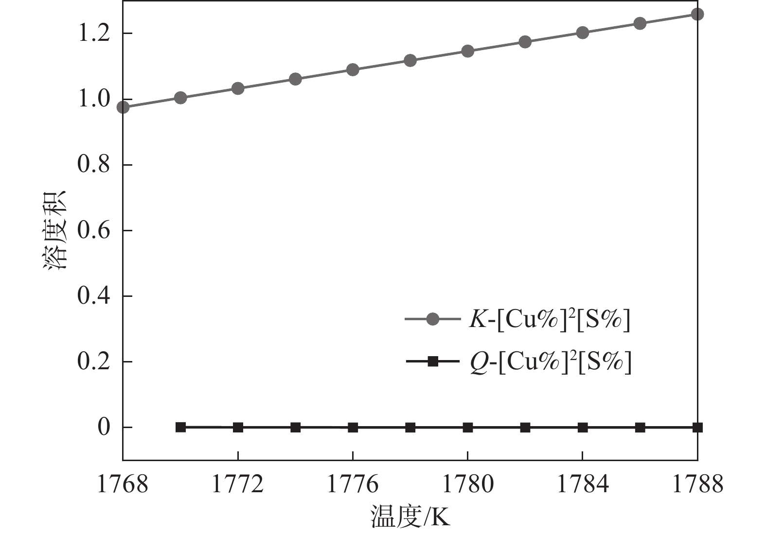
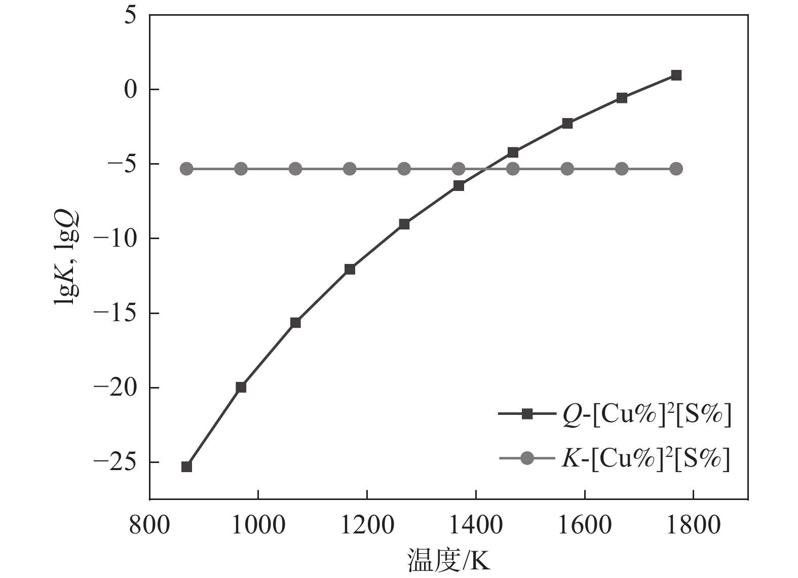
 图 9 凝固过程中Cu2S析出溶度积关系Figure 9. Relationship of solubility product of Cu2S precipitation and temperature during solidification process
AlN的溶度积关系如图6所示。可以看出Q和K曲线没有交点,且Q始终能够高于K,这说明实际溶度积高于平衡溶度积,即次过程有AlN析出。此外,从Q的变化趋势也可以知道,液相向固相转换过程中,溶质元素Al和N逐渐增高,因此其溶度积也在逐渐增加,从
1768 K时的0.023增加到1788 K时的0.029。由于Q>K,AlN在此温度范围内可以析出。由图7可知,从
1788 K降温到1770 K,在此过程中Q和K没有交点,但是Q始终大于K,这表明TiN在1788 ~1788 K温度范围内是可以析出的。综上所述,液相线和固相线之间的MnS溶度积关系如图8所示, MnS的Q和K曲线没有交点,但Q始终高于K,即MnS在此温度范围内是可以析出的。
同理,液相线和固相线之间的Cu2S溶度积关系如图9所示,Cu2S的Q和K曲线没有交点,且Q始终低于K值,此种情况下Cu2S不具备析出热力学条件。
3.2.2 完全α阶段
图10~13为高牌号50ZW350无取向硅钢凝固过程到完全α阶段,氮化物和硫化物的析出溶度关系。由图10可知,K和Q曲线相交点的横坐标为
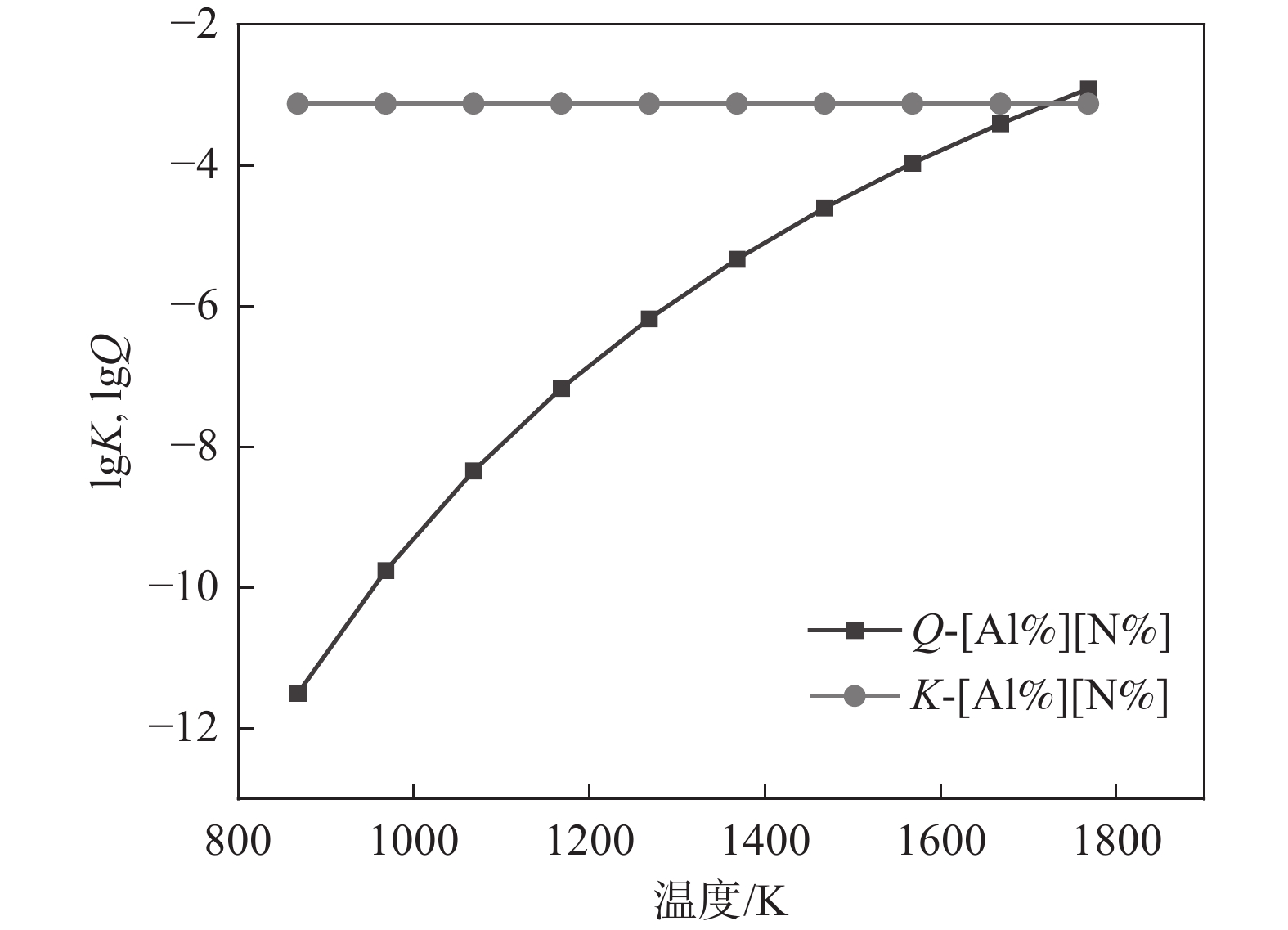
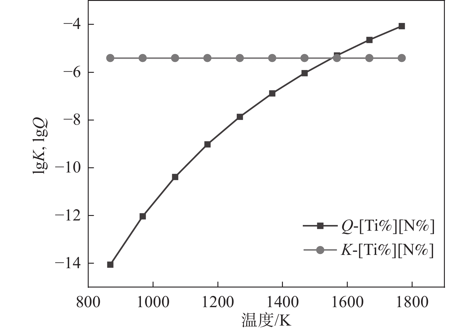
1700 K,即保持Q大于K的温度范围必须是1700 K以上,在此范围内AlN可以从凝固过程中析出。而TiN的Q和K曲线相交点横坐标为1588 K(见图11),也就是1588 K温度范围以上,TiN是能够从凝固过程中析出的。而MnS的Q和K不相交,且Q数值小于K(见图12),即MnS在此温度范围内不可能析出。Cu2S的Q和K曲线相交点的横坐标为1420 K(见图13),且在温度1420 K以上Q大于K时,Cu2S是可以析出的。 图 10 凝固过程中AlN析出溶度积关系Figure 10. Relationship of solubility product of AlN precipitation and temperature during solidification process
3.3 实际结果验证
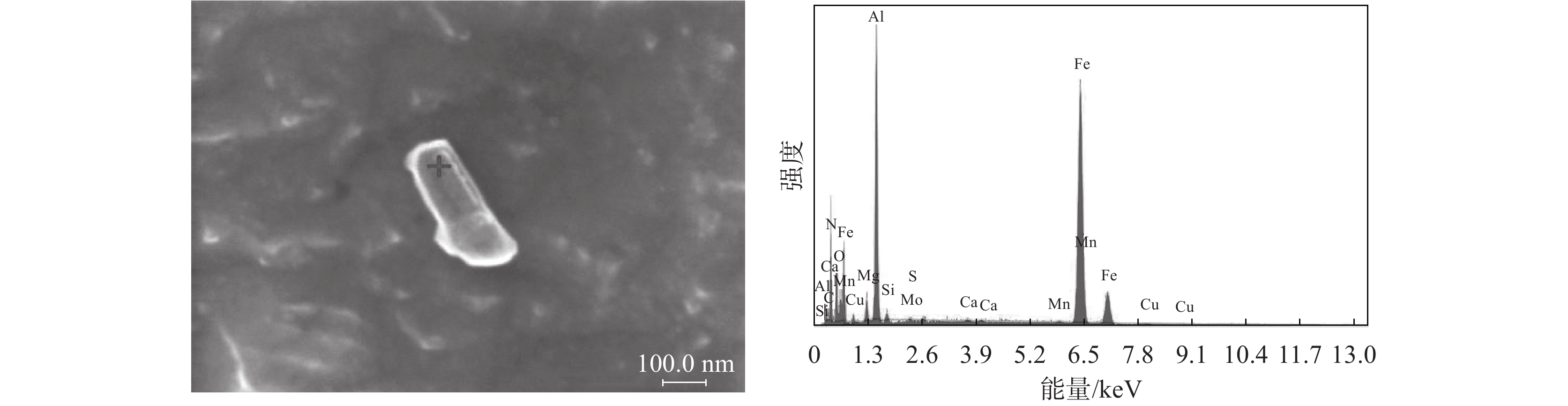
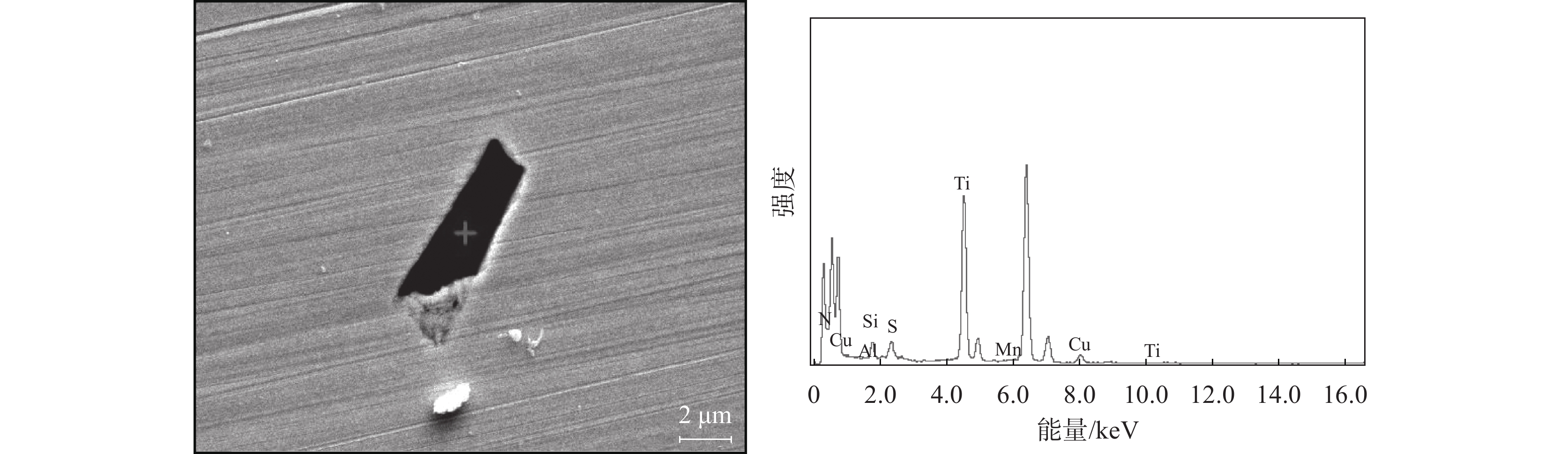
为了证明上述分析的准确性,仅从热轧板取试样,经过电解抛光,并在扫描电镜下观察。图14~17为实际检测到的结果。这也说明了上述分析的可行性。
 图 11 凝固过程中TiN析出溶度积关系Figure 11. Relationship of solubility product of TiN precipitation and temperature during solidification process
 图 12 凝固过程中MnS析出溶度积关系Figure 12. Relationship of solubility product of MnS precipitation and temperature during solidification process
 图 13 凝固过程中Cu2S析出溶度积关系Figure 13. Relationship of solubility product of Cu2S precipitation and temperature during solidification process
4. 结论
1)在钢液中即液相线温度以上,AlN、TiN、MnS和Cu2S均不能析出;
2)在凝固过程中即液相线温度以下,AlN在L→α阶段以及固相线以下部分温度段析出,即
1700 ~1788 K温度区间可能析出,TiN在L→α阶段以及固相线以下部分温度段析出,即1588 ~1788 K温度区间析出,MnS仅在L→α阶段,即1768 ~1788 K温度区间析出,Cu2S在固相线以下部分温度段,即1420 ~1768 K温度区间时析出。 -
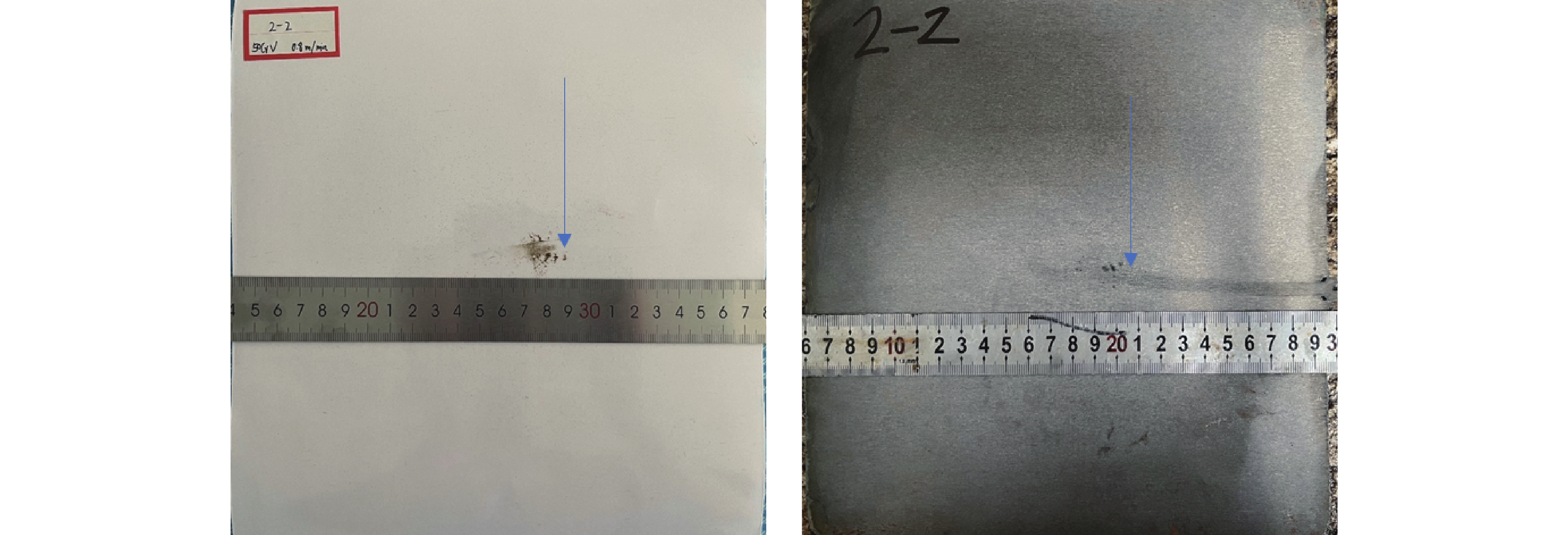
图 2 射钉试验结果照片(υ=0.8 m/min)
(a)硫印照片;(b)酸浸低倍组织照片
Figure 2. The results of the nail shooting experiment
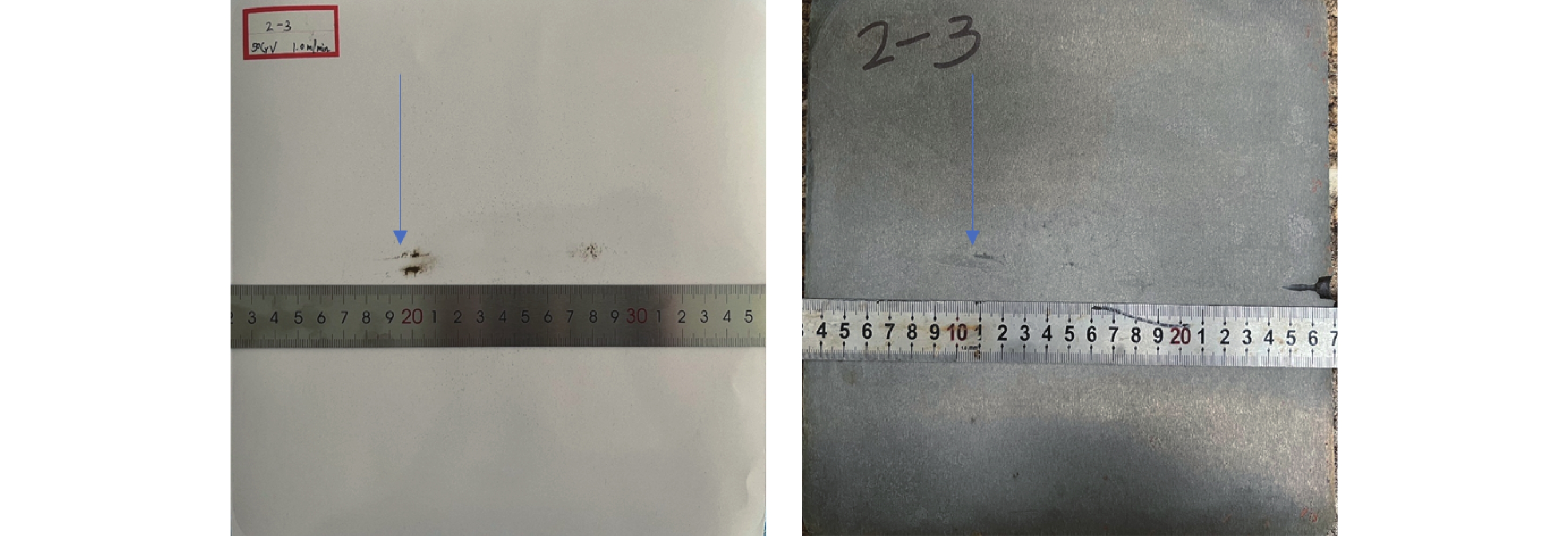
图 3 射钉试验结果照片(υ=1.0 m/min)
(a)硫印照片;(b)酸浸低倍组织照片
Figure 3. The results of the nail shooting experiment
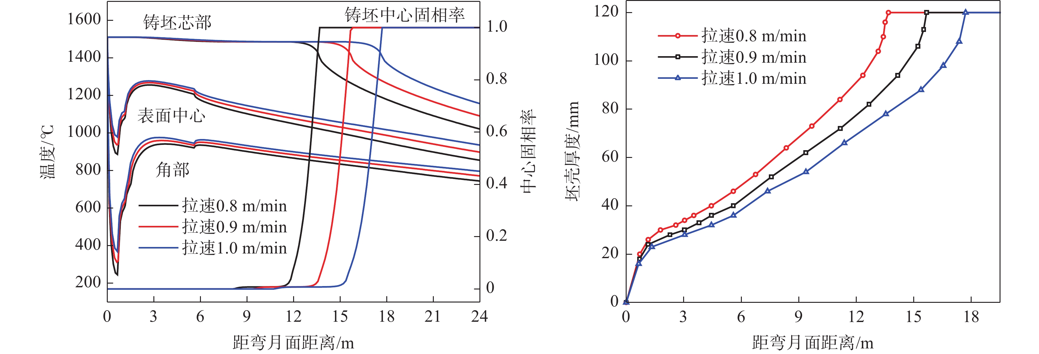
图 4 拉速对凝固过程的影响
(a)铸坯温度及中心固相率;(b)铸坯坯壳厚度
Figure 4. Effect of casting speed on the solidification process
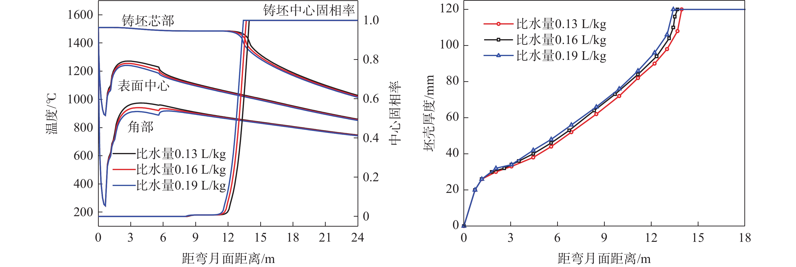
图 5 比水量对凝固过程的影响
(a)铸坯温度及中心固相率;(b)铸坯坯壳厚度
Figure 5. Effect of the specific water flow rate on the solidification process
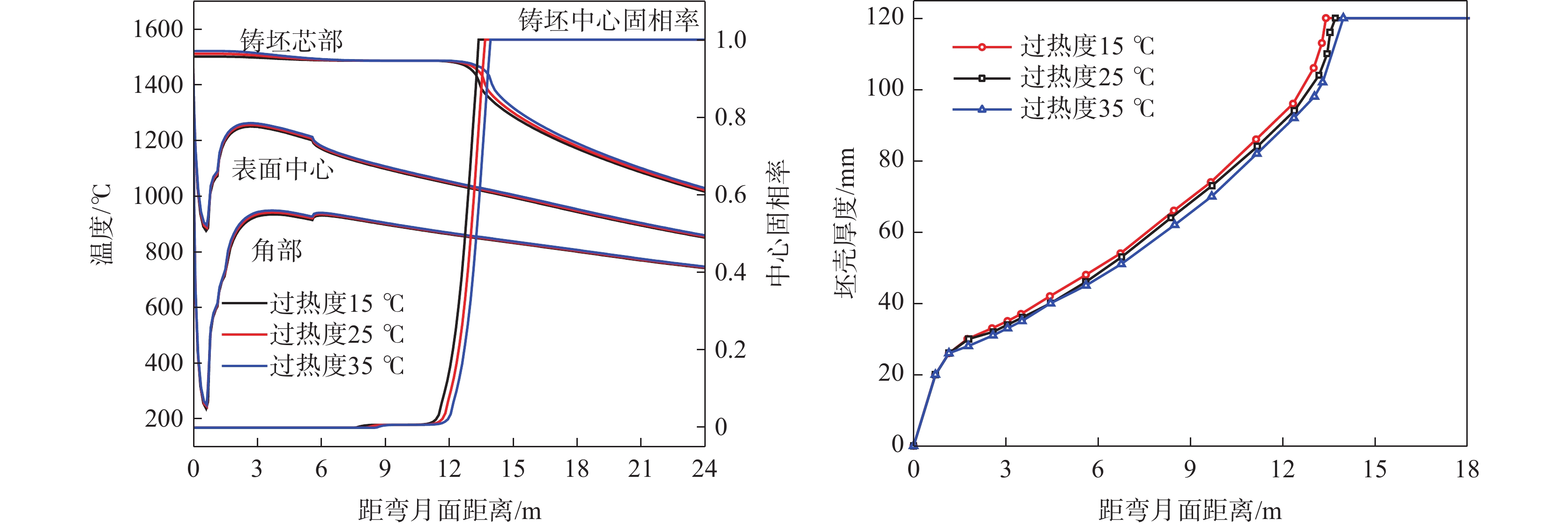
图 6 过热度对凝固过程的影响
(a)铸坯温度及中心固相率;(b)铸坯坯壳厚度
Figure 6. Effect of superheat on the solidification process
(a) Billet temperature and solid phase ratio at the center of billet; (b)thickness of casting shell
表 1 射钉化学成分
Table 1. Chemical composition of shoot nail used in this study %
钢种 C Si Mn Cr 其他 60Si2MnA 0.56~0.64 1.60~2.00 0.60~0.90 ≤0.35  下载: 导出CSV
表 2 50CrV钢的主要化学成分
Table 2. The main chemical compositions of 50CrV steel
% C Si Mn P S Cr V 0.50 0.26 0.69 0.009 0.004 1.03 0.12
下载: 导出CSV
表 3 50CrV方坯生产工艺条件
Table 3. 50CrV billet production process parameters
钢种 拉速/(m·min−1) 过热度/℃ 结晶器水量/(m3·h−1) 比水量/(L·kg−1) 冷却水量/(t·h−1) 足辊 Ⅰ区 Ⅱ区 Ⅲ区 50CrV 0.8 25 125 0.16 1.6 0.8 0.6 0.5 1.0 25 125 0.19 2.0 1.2 1.0 0.8
下载: 导出CSV
表 4 50CrV钢射钉试验结果
Table 4. The nail shooting experiment results of 50CrV billet
射钉序号 拉速/(m·min−1) 射钉位置/m 坯壳厚度/mm 平均坯壳厚度/mm 综合凝固系数K/(mm·min−1/2) 凝固终点位置/m 酸洗 硫印 2-2 0.8 12.4 92 92 92.0 26.7 16.2 2-3 1.0 12.4 75 75 75.0 26.9 19.8
下载: 导出CSV
表 5 现场末端电磁搅拌中心处液芯厚度及理想厚度
Table 5. measureed and ideal thickness of liquid core at the center of the electromagnetic stirring
钢种 末搅位置/m 拉速/(m·min−1) 末搅中心处液芯厚度/mm 计算值 理想值 50CrV 9.93 0.8 52 80 1.0 70
下载: 导出CSV
表 6 不同液芯厚度下凝固末端电磁搅拌中心适宜位置
Table 6. The appropriate position of the solidification end electromagnetic stirring center under different core thicknesses
拉速/(m·min−1) 比水量/(L·kg−1) 末搅中心距弯月面距离/m 液芯厚度80 mm 液芯厚度70 mm 液芯厚度60 mm 0.8 0.16 7.18 8.11 9.09 1.0 0.19 8.84 9.98 11.19
下载: 导出CSV
表 7 适宜现场(距弯月面9.93 m)处电搅发挥作用的拉速
Table 7. Casting speed suitable for electromagnetic stirring at the location 9.93 m below the meniscus
m/min 钢种 液芯厚度80 mm 液芯厚度70 mm 液芯厚度60 mm 50CrV 1.11 0.99 0.88
下载: 导出CSV
-
[1] WANG W B, HU S S, ZHANG M, et al. Effect of heat treatment process on surface condition and fatigue properties of 50CrVA spring steel[J]. Metal World, 2023(5):80-82. (王文博, 胡生双, 张锰, 等. 热处理工艺对50CrVA弹簧钢表面状态和疲劳性能的影响[J]. 金属世界, 2023(5):80-82. doi: 10.3969/j.issn.1000-6826.2022.02.0701WANG W B, HU S S, ZHANG M, et al. Effect of heat treatment process on surface condition and fatigue properties of 50CrVA spring steel[J]. Metal World, 2023(5): 80-82. doi: 10.3969/j.issn.1000-6826.2022.02.0701 [2] FAN Z W, ZHOU Z R, ZHANG Q, et al. Effect of precipitates in 50CrVA of automobile spring flat steel on its properties[J]. Hot Working Technology, 2022,51(21):98-101. (范众维, 周梓荣, 章庆, 等. 汽车弹簧扁钢50CrVA中析出物对其性能的影响[J]. 热加工工艺, 2022,51(21):98-101.FAN Z W, ZHOU Z R, ZHANG Q, et al. Effect of precipitates in 50CrVA of automobile spring flat steel on its properties[J]. Hot Working Technology, 2022, 51(21): 98-101. [3] LI J. Study on soft reduction process theory and central segregation of pressure vessel steel wide slab[D]. Beijing: University of Science and Technology Beijing, 2022. (李杰. 压力容器钢宽板坯轻压下工艺理论及中心偏析研究[D]. 北京: 北京科技大学, 2022.LI J. Study on soft reduction process theory and central segregation of pressure vessel steel wide slab[D]. Beijing: University of Science and Technology Beijing, 2022. [4] QIN F T, LIU Z H, DONG Z L, et al. Measurement of solidified shell of 240 mm × 240 mm casting bloom by nail-shooting technique and process optimization[J]. Special Steel, 2020,41(1):51-54. (秦凤婷, 刘宗辉, 董战利. 利用射钉法测量240 mm×240 mm铸坯凝固坯壳厚度及工艺优化[J]. 特殊钢, 2020,41(1):51-54. doi: 10.3969/j.issn.1003-8620.2020.01.013QIN F T, LIU Z H, DONG Z L, et al. Measurement of solidified shell of 240 mm × 240 mm casting bloom by nail-shooting technique and process optimization[J]. Special Steel, 2020, 41(1): 51-54. doi: 10.3969/j.issn.1003-8620.2020.01.013 [5] ZHANG P, SHI P Z, XIE S Z, et al. Solidification process simulation and process optimization of high strength steel slab[J]. Iron Steel Vanadium Titanium, 2023,44(2):132-140. (张攀, 时朋召, 谢世正, 等. 高强钢板坯凝固过程模拟与工艺优化[J]. 钢铁钒钛, 2023,44(2):132-140. doi: 10.7513/j.issn.1004-7638.2023.02.019ZHANG P, SHI P Z, XIE S Z, et al. Solidification process simulation and process optimization of high strength steel slab[J]. Iron Steel Vanadium Titanium, 2023, 44(2): 132-140. doi: 10.7513/j.issn.1004-7638.2023.02.019 [6] CHEN F, XU X J, YANG Z J, et al. Optimization of final electromagnetic stirring in continuous casting and quality of high-carbon steel billets[J]. Special Casting & Nonferrous Alloys, 2019,39(7):750-753. (陈丰, 许秀杰, 杨子江, 等. 连铸末端电磁搅拌工艺的优化与高碳钢铸坯质量[J]. 特种铸造及有色合金, 2019,39(7):750-753.CHEN F, XU X J, YANG Z J, et al. Optimization of final electromagnetic stirring in continuous casting and quality of high-carbon steel billets[J]. Special Casting & Nonferrous Alloys, 2019, 39(7): 750-753. [7] LIU T, LI Y G, SUN Y H, et al. Development and application of prediction model for solidification structure and segregation of 82B billet[J]. Continuous Casting, 2022(6):8-15. (刘添, 李曜光, 孙彦辉, 等. 82B小方坯凝固组织和偏析预测模型开发及应用[J]. 连铸, 2022(6):8-15.LIU T, LI Y G, SUN Y H, et al. Development and application of prediction model for solidification structure and segregation of 82B billet[J]. Continuous Casting, 2022(6): 8-15. [8] WANG L, SUN Y H, NIU A P, et al. Numerical simulation of heat transfer and solidification in X80 slab continuous casting[J]. Iron Steel Vanadium Titanium, 2018,39(6):143-149. (王璐, 孙彦辉, 牛阿朋, 等. X80板坯传热凝固数值模拟[J]. 钢铁钒钛, 2018,39(6):143-149. doi: 10.7513/j.issn.1004-7638.2018.06.023WANG L, SUN Y H, NIU A P, et al. Numerical simulation of heat transfer and solidification in X80 slab continuous casting[J]. Iron Steel Vanadium Titanium, 2018, 39(6): 143-149. doi: 10.7513/j.issn.1004-7638.2018.06.023 [9] ZHOU X L, LENG X G, PENG S H, et al. Application research on thickness measurement of solidified slab shell by pin-shotting[J]. Continuous Casting, 2015,40(6):25-29. (周秀丽, 冷祥贵, 彭世恒, 等. 基于“射钉法”的凝固坯壳厚度测定的应用研究[J]. 连铸, 2015,40(6):25-29.ZHOU X L, LENG X G, PENG S H, et al. Application research on thickness measurement of solidified slab shell by pin-shotting[J]. Continuous Casting, 2015, 40(6): 25-29. [10] PAN P, HOU D, GE W Y, et al. Position of electromagnetic stirring at solidification end of continuous casting billet and optimization of continuous casting process[J]. Continuous Casting, 2022(2):66-76+88. (潘鹏, 侯栋, 戈文英, 等. 连铸坯凝固末端电磁搅拌位置及连铸工艺优化[J]. 连铸, 2022(2):66-76+88.PAN P, HOU D, GE W Y, et al. Position of electromagnetic stirring at solidification end of continuous casting billet and optimization of continuous casting process[J]. Continuous Casting, 2022(2): 66-76+88. [11] LI Y G. Simulation study of macroscopic transmission phenomenon and central segregation in continuous casting process[D]. Beijing: University of Science and Technology Beijing, 2022. (李曜光. 连铸过程宏观传输现象及中心偏析的模拟研究[D]. 北京: 北京科技大学, 2022.LI Y G. Simulation study of macroscopic transmission phenomenon and central segregation in continuous casting process[D]. Beijing: University of Science and Technology Beijing, 2022. [12] ZHOU G T, CHEN J, HUANG B C, et al. Numerical simulation of solidification and heat transfer of Q355B slab during continuous casting[J]. Continuous Casting, 2023(02):43-51. (周国涛, 陈金, 黄标彩, 等. Q355B板坯连铸凝固传热行为数值模拟[J]. 连铸, 2023(02):43-51.ZHOU G T, CHEN J, HUANG B C, et al. Numerical simulation of solidification and heat transfer of Q355B slab during continuous casting[J]. Continuous Casting, 2023(02): 43-51. [13] LALLY B, BIEGLER L, HENEIN H. Finite difference heat-transfer modeling for continuous casting[J]. Metallurgical Transactions B, 1990,21(4):761-770. doi: 10.1007/BF02654255 [14] TIEU A K, KIM I S. Simulation of the continuous casting process by a mathematical model[J]. International Journal of Mechanical Sciences, 1997,39(2):185-192. doi: 10.1016/0020-7403(96)00052-5 [15] SHENG Y P, KONG X D, YANG Y L. Study on thermal boundary conditions in the mold for continuous casting[J]. China Mechanical Engineering, 2007(13):1615-1618. (盛义平, 孔祥东, 杨永利. 连铸结晶器传热边界条件研究[J]. 中国机械工程, 2007(13):1615-1618. doi: 10.3321/j.issn:1004-132X.2007.13.025SHENG Y P, KONG X D, YANG Y L. Study on thermal boundary conditions in the mold for continuous casting[J]. China Mechanical Engineering, 2007(13): 1615-1618. doi: 10.3321/j.issn:1004-132X.2007.13.025 [16] JING C, WANG X, JIANG M. Study on solidification structure of wheel steel round billet using FE-CA coupling modle[J]. Steel Research International, 2011,82(10):1173-1179. doi: 10.1002/srin.201000303 [17] CAI D W, LU J Z, DOU K, et al. Numerical modelling on solidification and heat transfer process of micro-alloyed steel bloom[J]. Continuous Casting, 2023(5):51-56. (蔡大为, 陆靖洲, 窦坤, 等. 微合金钢连铸方坯凝固传热过程数值模拟[J]. 连铸, 2023(5):51-56.CAI D W, LU J Z, DOU K, et al. Numerical modelling on solidification and heat transfer process of micro-alloyed steel bloom[J]. Continuous Casting, 2023(5): 51-56. [18] ZHANG X W, BAI X L, SHI L, et al. Numerical simulation of solidification temperature field of SWRH72B-S wire steel continuous casting billet[J]. Continuous Casting, 2023(1):18-23. (张小伟, 白晓路, 石磊, 等. SWRH72B-S绞线钢连铸小方坯凝固温度场数值模拟[J]. 连铸, 2023(1):18-23.ZHANG X W, BAI X L, SHI L, et al. Numerical simulation of solidification temperature field of SWRH72B-S wire steel continuous casting billet[J]. Continuous Casting, 2023(1): 18-23. -

 下载:
下载:
 点击查看大图
计量
- 文章访问数: 42
- HTML全文浏览量: 17
- PDF下载量: 5
- 被引次数: 0

