Physical-numerical simulation and application of optimization of flow control device in a single-stand slab tundish
-
摘要: 合理的控流装置结构和布局是提升中间包内钢液洁净度的关键。采用数值模拟与水力学模拟相结合的方法对某厂单流板坯中间包控流装置不同组合方式及位置的钢液流动行为、RTD曲线及夹杂物去除率进行分析,结果表明,在坝墙间距不变情况下,挡墙往长水口侧移动适当距离会延长钢液平均停留时间9.9 ~17.9 s、死区体积比例减小0.45~0.85个百分点、中间包低温区域减少,净化钢液的能力有所提升;在坝墙间距改变的情况下,坝墙间距过大可能会导致中间包浇注区钢液的紊乱,钢液平均停留时间延长不明显,死区体积比例反而增大0.33个百分点,中间包低温区域增大,夹杂物总去除率上升0.18个百分点。因此,坝墙间距为473.5 mm及挡墙与长水口距离为720 mm是较为理想的控流装置组合方式。采用优化方案后,中间包内钢液洁净度得到有效提升。Abstract: The reasonable structure and layout of flow control devices are crucial for improving the cleanliness of molten steel within the tundish in the continuous casting process. A combined approach using numerical simulation and physical modeling was employed to analyze the steel flow behavior, residence time distribution (RTD) curves, and inclusions removal rates for different combinations and positions of flow control devices in a single-strand slab tundish at a certain plant. The results indicate that when the distance between the dam and baffle remains constant, a suitable shift of the baffle wall towards the ladle shroud side can prolong the average residence time of the liquid steel by 9.9 s to 17.9 s, reduce the dead zone volume fraction by 0.45 to 0.85 percentage, and decrease the low-temperature region in the tundish, thereby enhancing the purification capability of the molten steel. However, when the distance between the dam and baffle is changed, an excessively large distance between them may cause turbulence in the casting zone of the tundish, with the average residence time of the steel showing no significant extension. Instead, the dead zone volume fraction increases by 0.33 percentage, leading to an enlargement of the low-temperature region in the tundish and a 0.18 percentage increase in the overall inclusion removal rate. Thus, a dam-to-dam distance of 473.5 mm and a baffle-to-ladle shroud distance of 720 mm are considered to be the more ideal combination for flow control device settings. The steel cleanness in the single-strand tundish has been effectively enhance by applying the optimized flow control scheme.
-
Key words:
- tundish /
- flow control device /
- physical and numerical modeling /
- RTD curves /
- inclusion removal
-
0. 引言
连铸技术的发展方向必然是向着高效、清洁、低能耗方面发展,而中间包作为钢液凝固前的最后容器,对铸坯质量有着很重要的作用[1−3]。合理的中间包流场对防止钢液二次氧化、钢液温度均匀化、促进夹杂物上浮等具有重要的作用[4−6]。因此通过在中间包内安装挡渣堰、导流坝以及湍流控制器等控流装置优化钢液的流动方向,以达到延长滞留时间、提升钢液洁净度的目的。
王家辉等[7−8]设计了一种顶旋型湍流抑制器,并利用物理模拟研究中间包内钢液运动状态,研究发现顶旋型湍流抑制器对中间包稳态浇注过程无负面影响,对非稳态浇注过程有明显改善效果。吴金强等[9]通过物理模拟的方法对某钢厂三流中间包进行结构优化,结果表明对原型中间包导流孔进行优化后,最优方案“U9-T1”的流体停留时间由原型的346.50 s延长至451.83 s,死区比例降至22.29%。薛伟锋等[10]采用水力学数理模拟的方法研究了不同尺寸和安装位置的控流装置对马钢薄板坯连铸中间包流动特性的影响,研究发现改进后的优化方案使中间包内示踪剂开始响应时间为无控流装置下的2倍多,平均停留时间由264.0 s增加到301.4 s,死区比例由无控流装置的25.54%降低到15.39%,中间包的冶金性能有了明显改进。陈登福等[11]采用物理和数值模拟方法对重钢24 t中间包进行了控流装置的优化研究,结果表明使用合适的湍流控制器和现有挡墙设置组合可以延长响应时间及平均停留时间,提高活塞流区体积分数30%及降低死区体积分数50%,中间包内流体流动特性得到改善。Quan等[12]用数理模拟研究了控流装置对单流板坯中间包内钢液流动及夹杂物去除率的影响,表明当采用挡堰-挡坝联合湍流抑制器的控流方案时,对70 μm以下的夹杂物去除率提高明显。数理模拟研究在一定程度上可以为中间包流场优化、提高钢液洁净度上提供一定的理论指导,结合相应的工业试验能直接反映控流装置的优化效果。以上研究者虽研究了控流装置对中间包冶金能力的影响,但并未对其进行综合全面分析。
笔者以某厂单流板坯中间包为对象,采用数值模拟和水力学物理模拟相结合的方法,对比分析该中间包内坝墙控流装置在间距不变和间距改变两种情况下的钢液流动、温度场、RTD曲线以及夹杂物去除率的变化规律,提出优化方案,并对优化后的控流方案进行工业试验,为生产现场钢液洁净度的提升提供指导。
1. 模型描述
1.1 基本假设
对单流板坯中间包中钢液复杂的湍流流动数值模拟做出以下假设:
1)中间包表面为自由表面,忽略中间包覆盖渣对流体的影响;
2)忽略中间包内夹杂物对钢液的影响及化学反应;
3)中间包内流体被视为不可压缩的牛顿流体;
4)忽略温度变化对中间包内流体流动的影响;
5)忽略夹杂物之间碰撞、聚合长大,且只被自由表面吸附。
1.2 控制方程
1.2.1 连续性方程
连续性方程[13]和动量方程[14]如式(1)和式(2)所示。
$$ \frac{\partial {\rho }_{\mathrm{m}}}{\partial t}+\nabla \cdot \left({\rho }_{\mathrm{m}}\overrightarrow{{V}_{\mathrm{m}}}\right)=0 $$ (1) $$ \frac{\partial \rho_{\mathrm{m}} \vec{v}_{\mathrm{m}}}{\partial t}+\nabla \cdot\left(\rho_{\mathrm{m}} \overrightarrow{V_{\mathrm{m}}} \overrightarrow{V_{\mathrm{m}}}\right)=-\nabla p+\mu_{\mathrm{m}} \nabla^2 \overrightarrow{V_{\mathrm{m}}}+\rho_{\mathrm{m}} \vec{g}$$ (2) 式中,$ \overrightarrow{{V}_{\mathrm{m}}} $是流体合速度,$ \mathrm{m}/\mathrm{s} $;ρm是流体密度,$ \mathrm{k}\mathrm{g}/{\mathrm{m}}^{3} $;$ {\mu{}}_{\text{m}} $是流体粘度,$ \mathrm{P}\mathrm{a}\cdot \mathrm{s} $;p为流动静压,$ \mathrm{P} $a。
1.2.2 湍流模型
钢液在中间包内的湍流行为是一个复杂的过程,本文采用标准的k-ɛ模型描述。
湍动能(k)方程如式(3)所示。
$$ \frac{\partial\left(\rho_{\mathrm{m}} k\right)}{\partial t}+\nabla \cdot\left(\rho_{\mathrm{m}} \overrightarrow{V_{\mathrm{m}}} k\right)=\nabla \cdot\left[\left(\mu_{\mathrm{eff}}+\frac{\mu_{t, m}}{\sigma_k}\right)\right]+G_k-\rho_{\mathrm{m}} \varepsilon$$ (3) 湍动能耗散率(ε)方程如式(4)所示。
$$ \begin{split} & \frac{\partial\left(\rho_{\mathrm{m}}\varepsilon\right)}{\partial t} + \nabla \cdot \left(\rho_{\mathrm{m}}\overrightarrow{V_{\mathrm{m}}}\varepsilon\right) = \nabla\cdot\left[\left(\mu_{\mathrm{eff}} + \frac{\mu_{t,\mathrm{m}}}{\sigma_k}\right)\nabla\varepsilon\right] + \\ & C_{1\varepsilon}\frac{\varepsilon}{k}G_k-C_{2\varepsilon}\rho_{\mathrm{m}}\frac{\varepsilon^2}{k}\end{split} $$ (4) $$ {\mu}_{\text{eff}}\text={\mu}_{\text{t}}+{\mu }_{\mathrm{m}} $$ (5) $$ \mu_{t,\mathrm{m}}=\rho_{\mathrm{m}} {C}_{\mu}k^2/\varepsilon $$ (6) 式中,$ \mu_{\text{eff}} $为湍流有效黏度系数;$ \mu\mathit{_{\text{t}}} $为湍流黏度系数;$ {G}_{k} $为由空间速度梯度产生的湍流动能;C1ɛ、C2ɛ、Cμ、σk、σε为常数,其值为C1ɛ=1.44、C2ɛ=1.92、Cμ=0.09、σk =1.3和σε=1.0。
1.2.3 传质模型
示踪剂在中间包内的扩散行为采用传质模型进行计算,如式(7)所示。
$$ \frac{\partial}{\partial t}\left(\rho c_x\right)+\nabla \cdot\left(\rho c_x u_j\right)-\left[\left(\rho D_q+\frac{\mu_{{k}}}{S c_{{k}}}\right) \nabla c_i\right]=S_{\mathrm{n}}$$ (7) 式中,ρ为示踪剂密度,$ \mathrm{k}\mathrm{g}/{\mathrm{m}}^{3} $;$ \mathit{{c}}_x $为新入钢液的质量分数;$ {u}_{j} $为j方向新钢液的速度,$ \mathrm{m}/\mathrm{s} $;$ \mathit{{D}_{{q}}} $为新入钢液的扩散系数;$ {\mu }_{{k}} $为湍流黏度;$ {S}{{c}}_{{k}} $为湍流施密特数;$ \mathit{{S}}_{{n}} $为涡动黏度。
1.2.4 能量传输模型[15−16]
能量传输方程如式(8)所示。
$$ \frac{\partial}{\partial_{x_i}}\left(\rho u_{\mathrm{z}} H\right)=\frac{\partial}{\partial_{x_1}}\left(k_{\mathrm{eff}} \frac{\partial T}{\partial_{x_1}}\right) $$ (8) 式中,$ {x}_{i} $为i方向坐标值;$ {{u}}_{{z}} $为新入钢液速度,$ \mathrm{m}/\mathrm{s} $;H为钢液热焓,$ \mathrm{J}/\mathrm{g} $;keff为有效导热系数;T为钢液温度,$ \mathrm{K} $。
1.2.5 离散相模型[17−18]
本文采用离散相(DPM)模型计算夹杂物在中间包内的运动行为。计算时,忽略包壁对夹杂物的吸附、夹杂物颗粒间碰撞、聚集和长大等相互作用,仅考虑夹杂物颗粒由于浮力上浮被中间包保护渣吸附去除,控制方程为如式(9)所示。
$$ \frac{\mathrm{d} u_{p i}}{\mathrm{d} t}=F_{\mathrm{D}}\left(u_{\mathrm{i}}-u_{{\mathrm{p i}}}\right)+\frac{\left(\rho_{\mathrm{p}}-\rho\right)}{\rho_{\mathrm{p}}} g_{\mathrm{p}}$$ (9) $$ {F}_{{\mathrm{D}}}=\frac{18\mu }{{\rho }_{{\mathrm{p}}}{d}_{{\mathrm{p}}}^{2}}\cdot \frac{{C}_{{\mathrm{D}}}Re}{24} $$ (10) $$ {{C}}_{\text{D}}={{\alpha}}_{\text{1}}+\frac{{{\alpha }}_{\text{2}}}{{Re}}+\frac{{{\alpha}}_{\text{3}}}{{R}{{e}}^{\text{2}}} $$ (11) $$ {Re=}\frac{\text{ρ}{{d}}_{\text{p}}\left|{{u}}_{\text{pi}}\text-{{u}}_{\text{i}}\right|}{\mu} $$ (12) 式中,$ {u}_{\mathrm{p}\mathrm{i}} $和$ {u}_{\mathrm{i}} $分别为夹杂物的瞬时速度和流体的瞬时速度,$ \mathrm{m}/\mathrm{s} $;$ {F}_{\mathrm{D}} $为曳力,$ \mathrm{N} $;$ {\rho }_{\mathrm{p}} $为粒子的密度, $ \mathrm{k}\mathrm{g}/{\mathrm{m}}^{3} $;$ {d}_{\mathrm{p}} $为粒子的直径,$ \mathrm{m} $;$ {g}_{\mathrm{p}} $为粒子重力加速度,$ \mathrm{m}/{\mathrm{s}}^{2} $;$ \mu $为动力黏性系数;$ {C}_{\mathrm{D}} $为曳力系数;${Re} $为雷诺数;$ {\alpha }_{1} $、$ {\alpha }_{2} $、$ {\alpha }_{3} $为常数。
1.3 RTD曲线的分析方法
RTD曲线是冶金学者用来评估中间包流场的一种重要方法,本文采用Zhang等[19]采用的分析方法:
理论平均停留时间ta计算公式为:
$$ {{t}}_{{a}}=\frac{{V}}{{Q}} $$ (13) 式中,$ V $是中间包体积,$ {\mathrm{m}}^{3} $;$ Q $是钢液的体积流速,$ {\mathrm{m}}^{3}/\mathrm{s} $。
实际平均停留时间计算如下:
$$ \bar{t}=\frac{\displaystyle\sum_{k=1}^N C\left(t_k\right) \cdot t_k}{\displaystyle\sum_{k=1}^N C\left(t_k\right)}, \quad t_k \in[0,+\infty]$$ (14) 两倍理论平均停留时间:
$$ \bar{t}_{\mathrm{c}}=\frac{\displaystyle\sum_{k=1}^N C\left(t_k\right) \cdot t_k}{\displaystyle\sum_{k=1}^N C\left(t_k\right)}, \quad t_k \in\left[\begin{array}{ll} 0, & 2 t_{\mathrm{a}} \end{array}\right] $$ (15) 死区体积分数:
$$ {V}_{{\mathrm{d}}}=1-\frac{\overline{{t}_{{\mathrm{c}}}}}{\overline{t}} $$ (16) 活塞区体积分数:
$$ {V}_{{\mathrm{p}}}=\frac{{t}_{{\mathrm{r}}}+{t}_{{\mathrm{p}}}}{2{t}_{{\mathrm{a}}}} $$ (17) 全混区体积分数:
$$ {V}_{{\mathrm{m}}}=1-{V}_{{\mathrm{d}}}-{V}_{{\mathrm{p}}} $$ (18) 式中,$ {t}_{{\mathrm{r}}} $为响应时间,$ \mathrm{s} $;$ {t}_{{\mathrm{p}}} $为峰值时间,$ \mathrm{s} $。
1.4 边界条件
1)中间包入口设为速度入口,速度大小由板坯尺寸和拉速根据质量守恒定律确定:$ {V}_{\text{in}}=Q/A $,Q为中间包入口流量,A为长水口截面积。入口处的湍动能和湍动能耗散率为:$ k=0.01\cdot {V}_{\text{in}}^{2} $,$ \varepsilon =2{k}^{1.5}/{D}_{\text{in}} $[20-21],$ {D}_{\text{in}} $为长水口直径。
2)出口类型为自由流出边界。
3)中间包液面为自由液面且平整无摩擦。
4)中间包对称面所有变量梯度为0。
5)中间包壁面采用无滑移壁面边界条件处理,近壁面采用标准壁面函数处理。
6)在稳态传热计算过程中,中间包入口钢液温度为
1751 K,中间包各对称面热流强度分别为15000 、3200 、3800 、1400 $ \text{W/}{\text{m}}^{\text{2}} $[22-24]。7)数值模拟过程中夹杂物颗粒与中间包壁面为完全弹性碰撞,出口面设置为“Escape”,上表面设置为“Trap”,其余壁面设置为“Reflect”。
1.5 计算模型设置
以某厂单流板坯中间包为对象,计算模型采用六面体网格,总网格数约为100万,中间包网格及计算所需工艺参数分别如图1和表1所示。
表 1 中间包数值模拟计算所用主要工艺参数Table 1. Main industrial parameters of tundish applied in the numerical simulations原中间包
工作吨
位/t原中间包
工作液
位/mm长水口
浸入
深度/mm铸坯断面
尺寸/
(mm×mm)典型拉坯
速度/
(m$ \cdot $min−1)长水口
内径/mm浸入式水口
内径/mm夹杂物
密度/
(kg$ \cdot $m−3)钢液物理
密度/
(kg·m−3)钢的摩尔
质量/
(g·mol−1)钢液黏度/
(Pa·s)22 994 400 1248 ×2001.1 75 62 3500 7000 55.86 0.0062 1.6 计算方案
通过对比分析原型中间包、坝墙位置整体移动和坝墙位置单项移动等方案中间包流场、RTD曲线及夹杂物去除率,获得较优控流装置方案,具体方案参数见表2。
表 2 单流板坯中间包数值模拟计算方案Table 2. Calculation scheme of single-strand tundish applied in the numerical simulations方案 编号 参数 挡墙距
长水口/mm坝墙中心
间距/mm挡坝距浸入
式水口/mm原型中间包 920 473.5 679 坝墙间距不变 A1 770 473.5 679 A2 720 473.5 679 A3 670 473.5 679 坝墙间距改变 B1 720 673.5 679 B2 920 673.5 479 2. 模型验证
中间包水力学模拟理论基础是相似原理,考虑到一般试验条件下流体流动已处于第二自模化区,在该系统下的流体流动状态及流速分布基本与雷诺数无关。因此,只要保证与重力有关的弗劳德数Fr相等即可达到动力相似[25−26]。比较20 ℃的水和
1600 ℃钢液的物理性质可知,水与钢液具有几乎相同的运动粘度,且水的价格低廉易取,故采用水力学试验模拟钢液流动过程。本研究采用相似比为1:2的中间包物理模型进行验证。同时,由Fr准数相等可以确定出模型和原型中间包内流体的速度、流量、平均停留时间的关系,结果见表3。表 3 中间包模型和原型参数比例Table 3. Tundish model and prototype parameter ratio线性比 速度比 流量比 平均停留时间比 公式 $ { \lambda } $ $ {{v}}_{\text{m}}\text{=}\sqrt{{ \lambda }}\text{∙}{{v}}_{\text{p}} $ $ {{Q}}_{\text{m}}\text{=}{{ \lambda }}^{\tfrac{\text{5}}{\text{2}}}\text{∙}{{Q}}_{\text{p}} $ $ {\overline{{t}}}_{\text{m}}\text{=}\dfrac{{{L}}_{\text{m}}{/}{{V}}_{\text{m}}}{{{L}}_{\text{p}}{/}{{V}}_{\text{p}}} $ 值 1/2 0.707 0.17678 0.707 注:$ \lambda $为线性比;下标p、m分别代表原型和模型;v、L分别为流速、特征长度。 2.1 示踪剂扩散
选取方案A2进行不同时间(28、95、141、360 s)示踪剂在水模型试验(左)和数值模拟(右)中扩散运动行为的对比。由图2可知,中间包内示踪剂在不同时间分布趋势基本相同,说明数值模拟采用的湍流模型是可信的。
2.2 RTD曲线
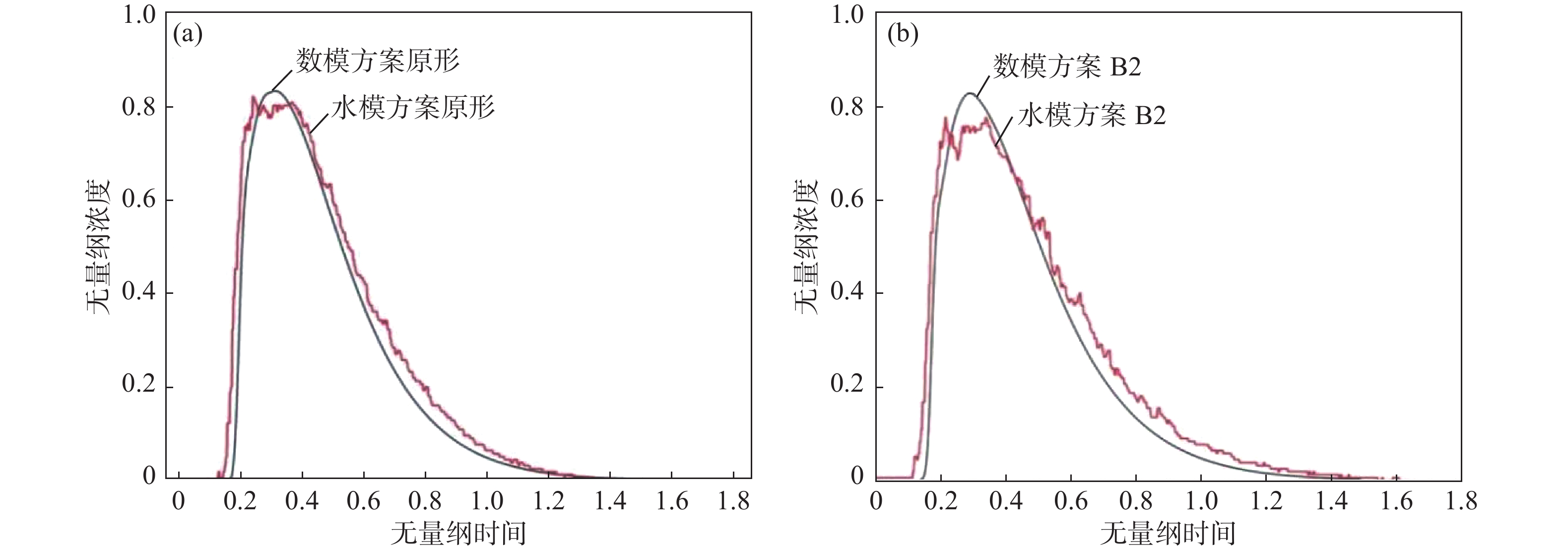
为验证数模结果的可靠性,对原型和方案B2两组数模和水模得到的RTD曲线进行对比,如图3所示。两者总体平均停留时间的误差比较见表4。由分析结果可得,水模试验和数值模拟RTD曲线趋势基本一致,且原型中间包和方案B2平均停留时间误差分别为5.4%和5.43%,两种模拟方法得到的 结果的相对误差均在合理范围之内。
表 4 原型中间包和方案B2水模试验和数值模拟平均停留时间误差对比Table 4. Comparison of average residence time between experiment and simulation under scheme B2 and prototype tundish方案 水模试验值/s 数值模拟/s 相对误差/% 原型 649.5 686.6 5.40 B2 649.5 686.8 5.43 3. 结果分析
3.1 流场
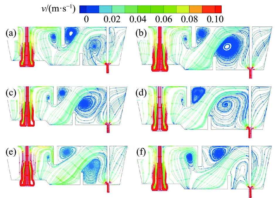
图4为数值模拟得出的原型及各控流方案下中间包流线。从图4可以看出,钢液首先通过钢包水口流入中间包冲击区,高速钢液经湍流抑制器作用会减弱钢液湍动能。但钢液仍会向中间包自由液面流动,这时钢液会在冲击区形成两个环流,一部分钢液与中间包壁发生碰撞回流;一部分钢液经挡墙作用后流向浇注区,随后钢液流速趋于稳定。
从中间包浇注区钢液流线可以看出,原型中间包由于挡墙中心距长水口较长,浇注区体积会较小。因此,钢液在浇注区形成的环流较弱,钢液不能充分的进行循环流动,从而导致过快流出中间包,缩短钢液平均停留时间,不利于夹杂物的上浮去除。而方案A1、A2、A3中间包在坝墙间距不变的情况下缩短了挡墙与长水口的距离,增大了浇注区体积,会使钢液流向浇注区时具有一定的冲击势能,形成的环流更明显,循环作用更强,使钢液在浇注区内的动量分布更为均匀。但浇注区体积不是越大越好,对比方案A2和方案A3,方案A3冲击区钢液明显速度过大,从而导致流向浇注区的钢液速度也会偏大。虽然浇注区钢液环流区域更大,但循环速度过快同样会使钢液更快流出中间包,缩短平均停留时间。方案B1和方案B2由于增大了坝墙间距,导致坝墙抬升钢液的作用力减弱,浇注区钢液没有充足的动能进行循环流动,同样会使钢液更快流出中间包,减少夹杂物上浮去除的机会,不利于洁净钢的生产。
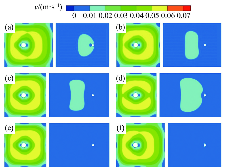
由于对中间包控流装置位置进行了调整,缩小中间包冲击区体积会增大钢液的湍流,导致中间包自由液面钢液速度过大。因此对原型中间包及各控流方案自由液面速度进行了分析,结果如图5所示。由图5可知,各方案中间包冲击区自由液面钢液速度均在0.07 m/s以下,浇注区自由液面钢液速度均在0.02 m/s左右,不会造成自由液面波动剧烈引起卷渣污染钢液等问题。
3.2 RTD曲线
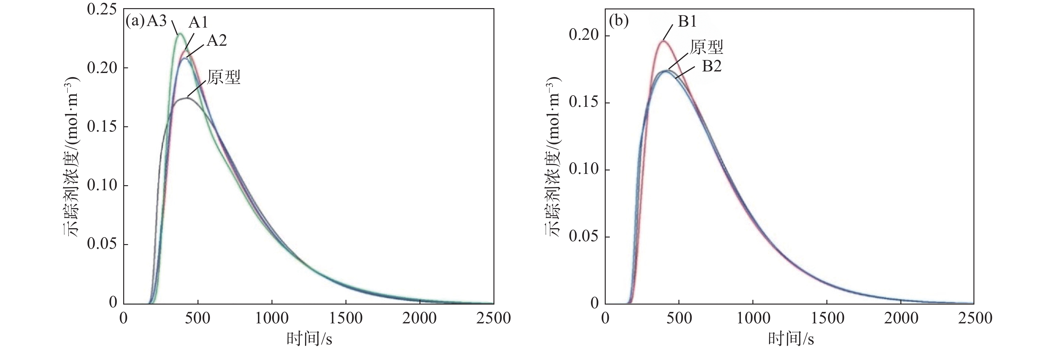
图6和表5分别为原型及各控流方案中间包RTD曲线和曲线分析结果。由图6和表5可以得出,方案A2中间包平均停留时间最长,为704.5 s,死区体积比例最小,为6.83%。相比原型中间包平均停留时间增加了17.9 s,死区体积比例减小了0.85个百分点。说明在坝墙间距不变情况下,减小挡墙与中间包长水口的间距能够有效地延长中间包内钢液的流动路径。由图4流线可知,方案A2中间包经坝墙作用后钢液速度达到0.04 m/s,钢液具有一定的冲击势能能够到达浇注区顶部,从而延长钢液在浇注区的流动路径,同时也能够增大浇注区环流的区域,增加夹杂物上浮的几率,提升钢液的洁净度。但在坝墙间距不变情况下挡墙与中间包长水口的间距不是越小越好,对比方案A3和方案A2,平均停留时间反而缩短了8 s,死区体积比例增大了0.63个百分点。方案A3中间包由于冲击区体积较小,从而导致挡墙右侧钢液涡流区域更大,死区体积比例会有所增大,经坝墙作用流向浇注区的钢液的速度也较大,由方案A3流线图可以看出,方案A3中间包浇注区自由液面的钢液一部分直接流向中间包下水口,另一部分参与钢液环流流动,因此会缩短平均停留时间。对比方案B1和方案A2, 其平均停留时间缩短了17 s,死区体积比例增大了0.74个百分点,说明在挡墙与中间包场水口间距不变的情况下,增大坝墙间距会减弱坝墙对钢液的作用力,导致钢液没有充足的动能流向浇注区远端区,缩短钢液在浇注区的流动路径。
对比原型和方案B2中间包,由图4流线图可得挡坝与浸入式水口间距较短会破坏浇注区环流作用,增加浇注区钢液的流动复杂性,具体表现在挡墙右侧区域涡流区增大及挡坝与塞棒处钢液的流动紊乱,方案B2死区体积比例相比原型反而增大了0.33个百分点。
表 5 各控流方案中间包RTD曲线分析结果Table 5. Analysis of RTD curves in the tundish under different schemes方案 $ {t}_{\mathrm{r}} $/s $ {t}_{\mathrm{p}} $/s $ \bar{t}/\mathrm{s} $ Vp/% Vd/% Vm/% 原型 171.0 421.0 686.6 43.11 7.68 49.21 A1 177.5 406.5 696.5 41.92 7.23 50.85 A2 179.0 414.5 704.5 42.12 6.83 51.05 A3 197.0 376.5 696.5 41.16 7.46 51.38 B1 167.0 391 687.5 40.58 7.57 51.85 B2 156.5 405.5 686.8 40.92 8.01 51.07 3.3 温度场
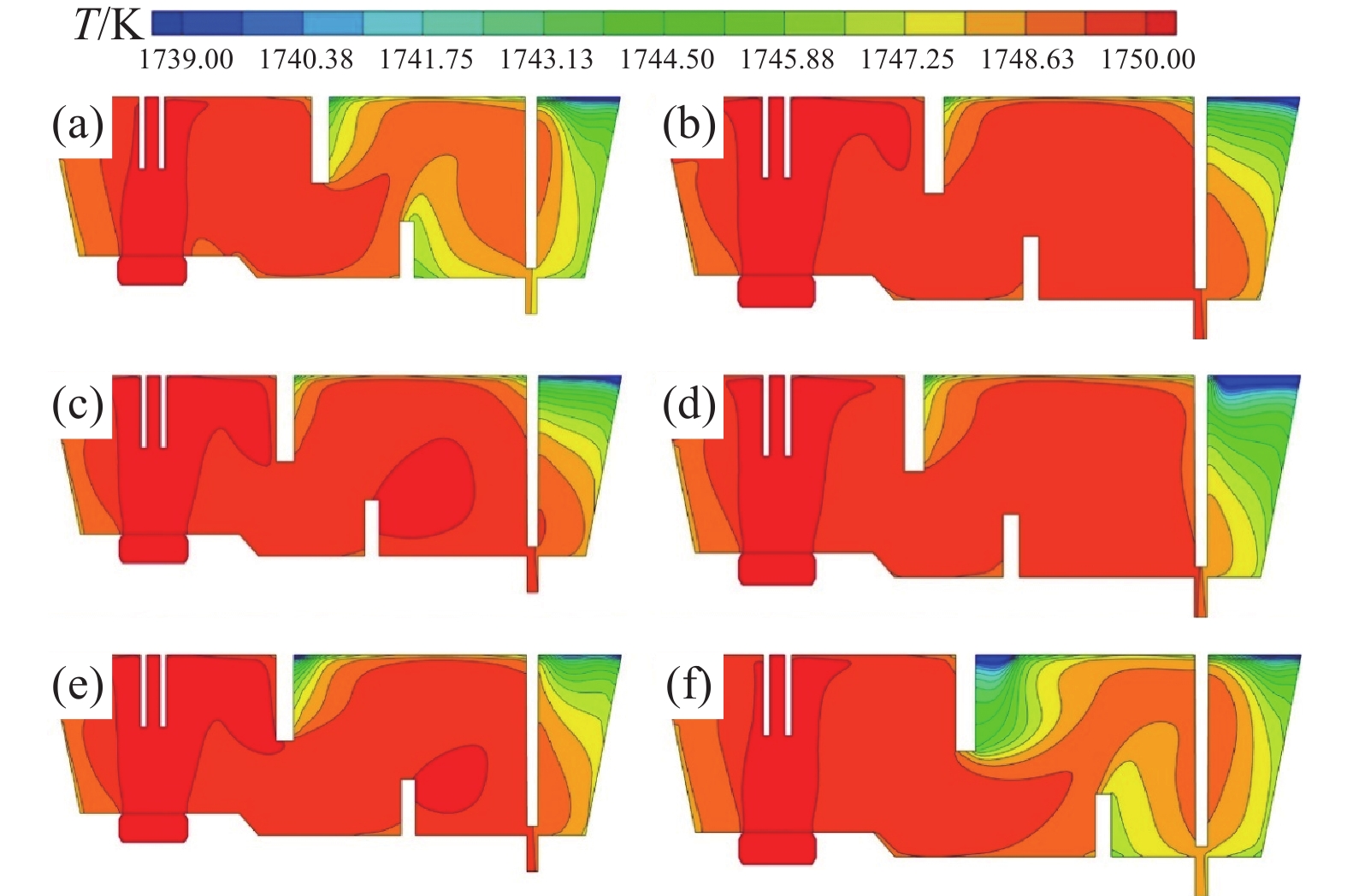
图7为各方案中间包长水口中心纵截面温度云图。由图7可以看出,各方案中间包内温度分布规律基本一致,原型中间包低温区域较为明显,出入口温差为3.1 K,说明原型中间包内流场具有一定的不合理性。经控流优化后方案A1、A2、A3中间包低温区域明显减少,出入口温差分别为2.4、1.7 K和2.6 K。其中,方案A2低温区域最少,出入口温差最小,这是由于方案A2流场较为合理,这与上文流场分析结果一致,对比方案A2和方案B1,方案B1中间包挡墙右侧低温区域有所增加,说明坝墙间距增大会减弱对钢液的作用力,使钢液更快流向出口。对比原型中间包和方案B2,方案B2中间包内温度分布明显更差,这是由于挡坝与中间包出口距离过小,破坏了浇注区钢液的环流作用,产生涡流,从而导致中间包低温区域过大。
3.4 夹杂物去除率
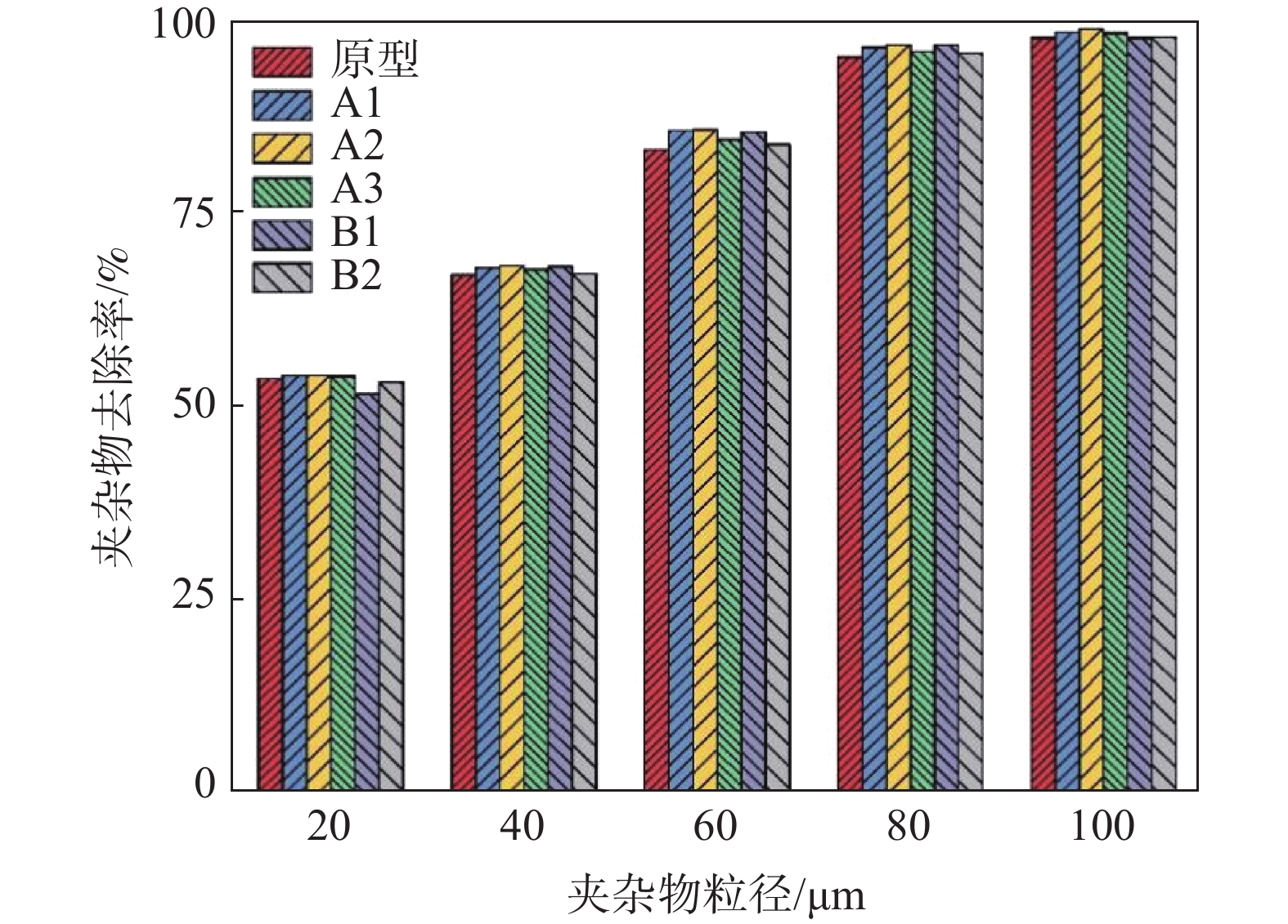
本研究夹杂物计算是在中间包稳态流场的基础上,运用DPM模型在中间包入口注入20 、40 、60 、80 μm和100 μm的夹杂物颗粒组,每种粒径的拉格朗日随机轨道模型尝试20次,每种夹杂物计算粒数约为
20000 ,最终各控流方案中间包夹杂物去除率及分析结果如图8所示。由图8可知,控流装置优化确实会提高中间包内夹杂物的去除能力,方案A1、A2、A3、B1、B2相较于原型方案整体平均去除率提高了1.15、1.40、0.74、0.59、0.18个百分点。对比方案A1、A2、A3中间包可以得出,在坝墙间距不变情况下挡墙与长水口距离过小反而会降低夹杂物的整体去除率。结合流线图和温度场结果,由于过小的冲击区体积会增加钢液的湍流复杂性,使流向浇注区的钢液速度较大,从而缩短其平均停留时间;且挡墙右侧区域钢液换热不充分,会降低夹杂物的去除率。对于小尺寸夹杂物(20~40 μm)去除率分析,方案A2中间包相较于原型平均提高0.8个百分点,且方案A2中间包100 μm夹杂物去除率高达99.04%。这是由于方案A2中间包流场及温度场分布整体较为合理,平均停留时间较长,夹杂物颗粒具有更充足的时间上浮去除。结合流场、温度场及RTD曲线分析可知,方案B1和B2相较原型中间包区别不大,因此夹杂物整体平均去除率相较原型仅提高0.59和0.18个百分点。说明对于当前中间包结构,增大坝墙间距对钢液洁净度的提升作用较小。
4. 工业应用效果
根据数理模拟研究结果,方案A2能有效增加钢液停留时间和夹杂物去除率,降低死区体积比。在某厂单流板坯中间包工业试验中,经过对近6个月生产的钢带进行跟踪取样分析,与优化前钢带夹杂物评级结果进行对比,如表6所示。
表 6 中间包优化前后夹杂物评级对比Table 6. Comparison of inclusions ranking before and after tundish optimization夹杂物评级/级 优化前占比/% 优化后占比/% B类 D类 B类 D类 0.5~1.0 26.44 97.95 32.42 100 1.5~2.5 70.33 2.05 66.59 0 >2.5 3.23 0 0.99 0 由表6可知,中间包控流方案优化所生产的不锈钢钢带内大尺寸夹杂物比例明显降低,B类夹杂≥1.5级的比例下降了5.98个百分点,>2.5级的比例由3.23%降至0.99%,且D类夹杂>1.0级的比例由2.05%降至0。钢带内夹杂物数量和尺寸有所减少,中间包钢液净化效果提升明显。
5. 结论
1)水模型试验和数值模拟中间包示踪剂在不同时间的趋势基本一致,且二者平均停留时间误差在5.4%左右,水模型试验能够较好的重现数值模拟结果,表明本研究数值模拟所采用的数学模型是可信的。
2)通过控流装置优化,改善了原型中间包浇注区钢液环流作用,方案A2(保持坝墙间距整体往长水口侧移动200 mm)中间包浇注区钢液环流作用较为明显,中间包自由液面钢液波动较小,出入口温差为1.7 K,平均停留时间相比原型延长17.9 s,死区体积比例相比原型缩小0.85个百分点。
3)控流装置优化能提高中间包夹杂物的去除能力,相比于原型,方案A2(保持坝墙间距整体往长水口侧移动200 mm)中间包夹杂物总去除率提高1.4个百分点,小尺寸夹杂物(20~40 μm)去除率平均提高0.8个百分点,100 μm夹杂物去除率高达99.04%。
4)采用优化控流方案后所生产的不锈钢钢带内大尺寸夹杂物去除率升高,中间包钢液洁净度得到有效提升。
5)本研究采用数理模拟及工业应用相结合的方法对中间包坝墙组合方式改进后冶金能力进行全面分析,可为钢铁企业对中间包控流装置优化提供理论指导。
-
表 1 中间包数值模拟计算所用主要工艺参数
Table 1. Main industrial parameters of tundish applied in the numerical simulations
原中间包
工作吨
位/t原中间包
工作液
位/mm长水口
浸入
深度/mm铸坯断面
尺寸/
(mm×mm)典型拉坯
速度/
(m$ \cdot $min−1)长水口
内径/mm浸入式水口
内径/mm夹杂物
密度/
(kg$ \cdot $m−3)钢液物理
密度/
(kg·m−3)钢的摩尔
质量/
(g·mol−1)钢液黏度/
(Pa·s)22 994 400 1248 ×2001.1 75 62 3500 7000 55.86 0.0062 表 2 单流板坯中间包数值模拟计算方案
Table 2. Calculation scheme of single-strand tundish applied in the numerical simulations
方案 编号 参数 挡墙距
长水口/mm坝墙中心
间距/mm挡坝距浸入
式水口/mm原型中间包 920 473.5 679 坝墙间距不变 A1 770 473.5 679 A2 720 473.5 679 A3 670 473.5 679 坝墙间距改变 B1 720 673.5 679 B2 920 673.5 479 表 3 中间包模型和原型参数比例
Table 3. Tundish model and prototype parameter ratio
线性比 速度比 流量比 平均停留时间比 公式 $ { \lambda } $ $ {{v}}_{\text{m}}\text{=}\sqrt{{ \lambda }}\text{∙}{{v}}_{\text{p}} $ $ {{Q}}_{\text{m}}\text{=}{{ \lambda }}^{\tfrac{\text{5}}{\text{2}}}\text{∙}{{Q}}_{\text{p}} $ $ {\overline{{t}}}_{\text{m}}\text{=}\dfrac{{{L}}_{\text{m}}{/}{{V}}_{\text{m}}}{{{L}}_{\text{p}}{/}{{V}}_{\text{p}}} $ 值 1/2 0.707 0.17678 0.707 注:$ \lambda $为线性比;下标p、m分别代表原型和模型;v、L分别为流速、特征长度。 表 4 原型中间包和方案B2水模试验和数值模拟平均停留时间误差对比
Table 4. Comparison of average residence time between experiment and simulation under scheme B2 and prototype tundish
方案 水模试验值/s 数值模拟/s 相对误差/% 原型 649.5 686.6 5.40 B2 649.5 686.8 5.43 表 5 各控流方案中间包RTD曲线分析结果
Table 5. Analysis of RTD curves in the tundish under different schemes
方案 $ {t}_{\mathrm{r}} $/s $ {t}_{\mathrm{p}} $/s $ \bar{t}/\mathrm{s} $ Vp/% Vd/% Vm/% 原型 171.0 421.0 686.6 43.11 7.68 49.21 A1 177.5 406.5 696.5 41.92 7.23 50.85 A2 179.0 414.5 704.5 42.12 6.83 51.05 A3 197.0 376.5 696.5 41.16 7.46 51.38 B1 167.0 391 687.5 40.58 7.57 51.85 B2 156.5 405.5 686.8 40.92 8.01 51.07 表 6 中间包优化前后夹杂物评级对比
Table 6. Comparison of inclusions ranking before and after tundish optimization
夹杂物评级/级 优化前占比/% 优化后占比/% B类 D类 B类 D类 0.5~1.0 26.44 97.95 32.42 100 1.5~2.5 70.33 2.05 66.59 0 >2.5 3.23 0 0.99 0 -
[1] Pan Hongwei, Wang Leichuan, Guan Shunkuan, et al. Inclusions movement behavior in tundish after ladle changing[J]. Iron Steel Vanadium Titanium, 2017,38(1):113-117. (潘宏伟, 王雷川, 关顺宽, 等. 换包后中间包内夹杂物运动行为[J]. 钢铁钒钛, 2017,38(1):113-117.Pan Hongwei, Wang Leichuan, Guan Shunkuan, et al. Inclusions movement behavior in tundish after ladle changing[J]. Iron Steel Vanadium Titanium, 2017, 38(1): 113-117. [2] Gao Wenxing, Yuan Jibai, He Junfeng, et al. Optimization of flow control device on twin channel induction heating tundish by simulation[J]. Iron Steel Vanadium Titanium, 2023,44(3):144-151. (高文星, 袁己百, 赫俊峰, 等. 双通道感应加热中间包控流装置模拟优化[J]. 钢铁钒钛, 2023,44(3):144-151.Gao Wenxing, Yuan Jibai, He Junfeng, et al. Optimization of flow control device on twin channel induction heating tundish by simulation[J]. Iron Steel Vanadium Titanium, 2023, 44(3): 144-151. [3] Sun Hua, Sun Yanhui, Huang Bo, et al. Simulation optimization research of tundish under different pull speeds[J]. Iron Steel Vanadium Titanium, 2017,38(3):118-123. (孙华, 孙彦辉, 黄博, 等. 三流非对称中间包流场水模拟研究[J]. 钢铁钒钛, 2017,38(3):118-123.Sun Hua, Sun Yanhui, Huang Bo, et al. Simulation optimization research of tundish under different pull speeds[J]. Iron Steel Vanadium Titanium, 2017, 38(3): 118-123. [4] Sahai Y. Tundish technology for casting clean steel: A review[J]. Metallurgical and Materials Transactions B, 2016,47(4):2095. doi: 10.1007/s11663-016-0648-3 [5] Huang Jun, Yuan Zhigang, Shi Shaoyuan, et al. Flow characteristics for two-strand tundish in continuous slab casting using PIV[J]. Metals, 2019,9(2):239. doi: 10.3390/met9020239 [6] Ni P, Jonsson I T L, Ersson M, et al. Application of a swirling flow producer in a conventional tundish during continuous casting of steel[J]. ISIJ International, 2017,57(12):2175. doi: 10.2355/isijinternational.ISIJINT-2017-377 [7] Wang Jiahui, Zhang Hua, Fang Qing, et al. Physical simulation on optimization of flow field in a tundish by top swirling turbulence inhibitor[J]. Iron and Steel, 2023,58(2):72. (王家辉, 张华, 方庆, 等. 顶旋型湍流抑制器优化中间包流场的物理模拟[J]. 钢铁, 2023,58(2):72.Wang Jiahui, Zhang Hua, Fang Qing, et al. Physical simulation on optimization of flow field in a tundish by top swirling turbulence inhibitor[J]. Iron and Steel, 2023, 58(2): 72. [8] Wang Jiahui, Fang Qing, Zhu Shuang, et al. Effect of top-swirling turbulence inhibitor on flow behaviors of a single-strand slab casting tundish[J]. Journal of Iron and Steel Research, 2021,33(7):575. (王家辉, 方庆, 朱爽, 等. 顶旋型湍流抑制器对单流板坯中间包内湍流行为的影响[J]. 钢铁研究学报, 2021,33(7):575.Wang Jiahui, Fang Qing, Zhu Shuang, et al. Effect of top-swirling turbulence inhibitor on flow behaviors of a single-strand slab casting tundish[J]. Journal of Iron and Steel Research, 2021, 33(7): 575. [9] Wu Jinqiang, Yang Shufeng, Li Jingshe, et al. Physical simulation of structure optimization of three-strand tundish[J]. China Metallurgy, 2019,29(11):39. (吴金强, 杨树峰, 李京社, 等. 三流中间包结构优化物理模拟[J]. 中国冶金, 2019,29(11):39.Wu Jinqiang, Yang Shufeng, Li Jingshe, et al. Physical simulation of structure optimization of three-strand tundish[J]. China Metallurgy, 2019, 29(11): 39. [10] Xue Weifeng, Wen Guanghua, Tang Ping, et al. Physical simulation of structure optimization of three-strand tundish[J]. Special Steel, 2005,26(3):19-21. (薛伟锋, 文光华, 唐萍, 等. 薄板坯连铸中间包控流装置的数理模拟[J]. 特殊钢, 2005,26(3):19-21. doi: 10.3969/j.issn.1003-8620.2005.03.006Xue Weifeng, Wen Guanghua, Tang Ping, et al. Physical simulation of structure optimization of three-strand tundish[J]. Special Steel, 2005, 26(3): 19-21. doi: 10.3969/j.issn.1003-8620.2005.03.006 [11] Chen Dengfu, Zuo Xiangjun, Zheng Hui, et al. Physical and mathematical study on flow control device of tundish for 5-strand billet casting at Chongqing steel[J]. Special Steel, 2007,28(1):1-3. (陈登福, 佐祥均, 郑辉, 等. 重钢5流方坯连铸中间包控流装置的数理研究[J]. 特殊钢, 2007,28(1):1-3. doi: 10.3969/j.issn.1003-8620.2007.01.001Chen Dengfu, Zuo Xiangjun, Zheng Hui, et al. Physical and mathematical study on flow control device of tundish for 5-strand billet casting at Chongqing steel[J]. Special Steel, 2007, 28(1): 1-3. doi: 10.3969/j.issn.1003-8620.2007.01.001 [12] Quan Qi, Zhang Zhixiao, Qu Tianpeng, et al. Physical and numerical investigation on fluid flow and inclusion removal behavior in a single-strand tundish[J]. Journal of Iron and Steel Research International, 2023,30(6):1182-1198. doi: 10.1007/s42243-022-00884-3 [13] Xu Rui, Ling Haitao, Wang Haijun, et al. Investigation on the effects of ladle change operation and tundish cover powder on steel cleanliness in a continuous casting tundish[J]. Steel Research International, 2021,92(10):2100072. doi: 10.1002/srin.202100072 [14] Chatterjee S, Li Donghui, Chattopadhyay K. Modeling of liquid steel/slag/argon gas multiphase flow during tundish open eye formation in a two-strand tundish[J]. Metallurgical and Materials Transactions B, 2018,49(2):756. doi: 10.1007/s11663-018-1177-z [15] Zhao Mengjing, Wang Yong, Yang Shufeng, et al. Flow field and temperature field in a four-strand tundish heated by plasma[J]. Metals, 2021,11(5):722. doi: 10.3390/met11050722 [16] Chatterjee Saikat, Li Donghui, Leung Jackie, et al. Investigation of eccentric open eye formation in a slab caster tundish[J]. Metallurgical and Materials Transactions B, 2017,48(2):1035. doi: 10.1007/s11663-016-0899-z [17] Xie Xuqi, Fang Qing, Wang Jiahui, et al. Numerical and physical simulation on enhancing steel cleanliness by increasing height of two-strand slab tundish[J]. China Metallurgy, 2023,33(6):95. (谢旭琦, 方庆, 王家辉, 等. 双流板坯中间包加高提升钢液洁净度的数理模拟[J]. 中国冶金, 2023,33(6):95.Xie Xuqi, Fang Qing, Wang Jiahui, et al. Numerical and physical simulation on enhancing steel cleanliness by increasing height of two-strand slab tundish[J]. China Metallurgy, 2023, 33(6): 95. [18] Zhao Peng, Zhang Hua, Fang Qing, et al. Numerical study on strand-blocking operation of a six-strand square billet tundish[J]. Journal of Iron and Steel Research, 2022,34(5):438. (赵鹏, 张华, 方庆, 等. 六流小方坯中间包堵流浇注的数值模拟研究[J]. 钢铁研究学报, 2022,34(5):438.Zhao Peng, Zhang Hua, Fang Qing, et al. Numerical study on strand-blocking operation of a six-strand square billet tundish[J]. Journal of Iron and Steel Research, 2022, 34(5): 438. [19] Zhang Hua, Wang Jiahui, Fang Qing, et al. Effect of top-swirling turbulence inhibitor on multiphase flow in a single‐strand tundish during transient casting[J]. Steel Research International, 2022,93(5):2100536. doi: 10.1002/srin.202100536 [20] Chen Xiqing, Xiao Hong, Wang Pu, et al. Three-dimensional magneto-hydrothermal coupling model of twin-channel tundish with induction heating[J]. Iron and Steel, 2021,56(6):48. (陈希青, 肖红, 王璞, 等. 双通道感应加热中间包的三维磁流热耦合模型[J]. 钢铁, 2021,56(6):48.Chen Xiqing, Xiao Hong, Wang Pu, et al. Three-dimensional magneto-hydrothermal coupling model of twin-channel tundish with induction heating[J]. Iron and Steel, 2021, 56(6): 48. [21] Li Yihong, Bao Yanping, Zhao Lihua, et al. Effect of diversion hole on flow trajectory of steel in multi-strand tundish[J]. Iron and Steel, 2014,49(6):37. (李怡宏, 包燕平, 赵立华, 等. 多流中间包导流孔对钢液流动轨迹的影响[J]. 钢铁, 2014,49(6):37.Li Yihong, Bao Yanping, Zhao Lihua, et al. Effect of diversion hole on flow trajectory of steel in multi-strand tundish[J]. Iron and Steel, 2014, 49(6): 37. [22] Ding Changyou, Lei Hong, Chen Shifu, et al. Challenge of residence time distribution curve in tundish for continuous casting of steel[J]. Steel Research International, 2022,93(10):2200187. doi: 10.1002/srin.202200187 [23] Zhang Hua, Fang Qing, Liu Chao, et al. Effect of flow control devices on grade change process in a five-strand tundish[J]. Metallurgical Research & Technology, 2022,119(3):317. [24] Fang Qing, Zhang Hua, Luo Ronghua, et al. Optimization of flow, heat transfer and inclusion removal behaviors in an odd multistrand bloom casting tundish[J]. Journal of Materials Research and Technology, 2020,9(1):347. doi: 10.1016/j.jmrt.2019.10.064 [25] Li Quanhui, Qin Bangming, Zhang Jiangshan, et al. Design improvement of four-strand continuous-casting tundish using physical and numerical simulation[J]. Materials, 2023,16(2):849. doi: 10.3390/ma16020849 [26] Ruan Yanwei, Yao Yu, Shen Shiyi, et al. Physical and mathematical simulation of surface-free vortex formation and vortex prevention design during the end of casting in tundish[J]. Steel Research International, 2020,91(6):1900616. doi: 10.1002/srin.201900616 -


 下载:
下载:


 下载:
下载:

