

Research on activator enhanced acid leaching process of titanium concentrate
-
摘要: 针对硫酸法钛白生产中反应酸浓度较高导致不能实现硫酸平衡的问题,通过引入活化剂强化酸解反应过程,降低反应酸浓度。研究了活化剂对钛精矿低浓度酸浸的强化作用,考察了反应酸浓度和活化剂加量对反应温度和钛浸出率的影响。结果表明:活化剂的加入,可以增加反应放热量,提高反应温度,并改善固相物的疏松度,浸出活性更高;活化剂加量为0.5%、酸矿比为1.56∶1,反应酸浓度为80%的条件下,钛精矿的钛浸出率达到93.47%;酸浸残渣主要成分为TiFeO3、Ca(Fe, Mg)Si2O6和SiO2,表明原料中的钛大部分被转移到液相中。Abstract: In response to the problem of high reaction acid concentration in the production of titanium dioxide by sulfuric acid method, which leads to the inability to achieve sulfuric acid equilibrium, an activator is introduced to enhance the acid hydrolysis reaction process and reduce the reaction acid concentration. The strengthening effect of the activator on the low concentration acid leaching of titanium concentrate was studied, and the effects of reaction acid concentration and activator dosage on reaction temperature and acid leaching rate were investigated. The results show that the addition of activating agent can increase the heat release of the reaction, increase the reaction temperature, and improve the porosity of the solid phase, resulting in higher leaching activity. Under the conditions of 0.5% activator dosage, 1.56:1 acid to ore ratio, and 80% reaction acid concentration, the acid hydrolysis rate of titanium concentrate reaches 93.47%. The main components of acid leaching residue are TiFeO3, Ca(Fe, Mg)Si2O6 and SiO2, indicating that most of the titanium in the raw material can be transferred to the liquid phase.
-
Key words:
- titanium concentrate /
- acid leaching /
- activator /
- solid phase
-
0. 引言
钛白粉是一种重要的无机材料,据统计,2023年全国钛白粉总产量416万t,其中,氯化法钛白粉的综合产量为69.2万t,硫酸法产量为346.8万t,占83.37%[1]。硫酸法每生产1 t钛白粉需要消耗98%浓硫酸约3.8 t,产生20%废酸6~8 t和副产物硫酸亚铁2.5~3.0 t[2−4]。因此,为解决硫酸法钛白生产过程中大量废酸的问题,研究一种钛精矿低反应酸浓度酸浸技术,提高20%废酸的回用量,降低98%硫酸的用量,降低“三废”处理成本及环保压力,具有重要的科学意义和广阔的工业应用前景。
钛精矿酸浸反应属于液-固异相反应,可以用整体反应模型和收缩未反应芯两种动力学模型进行描述。前期学者的研究表明,H2SO4 分解钛精矿的过程相当复杂,包括两个液膜扩散、两个固体膜扩散和一个化学反应过程,属于膜扩散与化学反应混合控制过程,反应过程中加强H2SO4与钛精矿之间的传质非常重要[5−7]。Wang Xiaomei等[8]发现,研磨过程会增加钛精矿的晶格变形和非晶化,降低浸出过程中的活化能。与干法研磨相比,湿法研磨更有效,湿法研磨后钛精矿的粒度更小、分布更均匀。此外,吴健春等[9]研究了预混工艺对钛精矿酸浸的影响,结果发现酸矿混合不均匀、酸浸反应不完全是产生大量酸浸难浸取固相物的主要原因,采用稀酸代替水与浓硫酸配制反应用酸可有效降低酸温,保证预混充分。但是,研磨浸出工艺对材料的耐酸性和耐磨性均有较高要求,并且能耗高。而化学强化酸浸的方式因其无需改造设备、添加量少、成本低而受到广泛关注。
表面活性剂是一种常见的活化剂,主要是通过改变矿石表面湿润性、降低浸出液黏度、强化吸附和渗透等作用强化浸出[10−11]。目前,关于活化剂改善矿石酸浸的研究报道涉及磷矿、锰矿、钨矿等。吴爱祥等[12]为解决高含泥铜矿石渗透性差和浸出率低的问题,通过添加表面活性剂改变矿石润湿性、降低浸出液黏度、吸附在矿石表面和增强渗透作用,使矿石的浸出率提高8.4%。田鸿等[13]合成了两性表面活性剂(AS-S),能降低溶液表面张力,进而提高浸出剂在矿石表面的铺展能力,渗透速率增大,可使锰浸出率达98.45%。
针对钛精矿酸浸反应特点,在不改变现有酸浸工艺基础上,通过加入酸浸活化剂强化低酸浓度下钛精矿酸浸过程。比较活化剂对酸浸反应放热、固相物结构和浸出特性的影响,探讨提高酸浸反应活性和固相物的疏松性, 达到降低反应酸浓度的目的,提高20%废酸回用率,对钛白行业的绿色持续发展具有十分重要的意义。
1. 试验部分
1.1 条件
钛精矿,平均粒径18 μm,来自攀钢集团重庆钛业有限公司,TiO2含量47.13%;硫酸(98%,CP)和盐酸(35%,CP)均购自成都科隆化学品有限公司,碳酸氢钠、硫氰酸钾、硫酸高铁铵、焦硫酸钾等均为AR,购自国药集团化学试剂有限公司。
利用X射线衍射分析仪(XRD-7000,日本津岛公司,扫描范围10°~80°,扫描速度2°/min,测试电压40 kV,测试电流30 mA)进行物相组成分析。利用场发射扫描电镜仪和能谱仪(SEM、EDS,Thermo Scientific APREO 2C,赛默飞世尔科技公司)对残渣分别进行微观形貌和元素分析。酸浸残渣成分分析采用荧光仪(Axios MAX,PANalytical)。
1.2 方法
1.2.1 钛精矿酸浸
称取计量的98% H2SO4加入酸浸反应釜中,开启搅拌(转速200 r/min),依次加入计量的钛精矿和引发水,打开加热,预热至140 ℃后停止加热,观察反应体系升温情况,达到最高反应温度后立即停止搅拌,然后在160 ℃下熟化2.5 h。熟化结束后,自然冷却至70 ℃以下,加入计量的蒸馏水,在70 ℃下浸取2 h。最后,将浸取后的悬浮液进行过滤,滤饼在120 ℃下干燥12 h,称取质量记为m,滤液量取体积记为V。
活化剂强化钛精矿酸浸,先将计量的活化剂与钛精矿混合均匀再进行酸浸。
1.2.2 分析方法
滤液和残渣中TiO2的含量按参考文献[14]中硫酸铁铵滴定法进行分析。根据公式(1)计算钛精矿中钛浸出率η。
$$ \eta =\frac{C\times V}{m\times W+C\times V}\times 100\% $$ (1) 式中,$ \eta $为钛浸出率,%; C为浸出液中TiO2质量浓度,g/L;m为质量,g;W为浸出残渣中TiO2的质量分数,%;V为浸出液体积,L。
2. 结果与讨论
2.1 硫酸法钛白生产废酸平衡分析
硫酸法生产钛白工业中,硫酸与钛精矿的质量比(酸矿比)1.54~1.56∶1,反应酸浓度为84%~85%,则生产1 t钛白98% H2SO4的消耗量约为3.5 t,同时会产生20%废酸量为6~8 t。如需要将产生的20%废酸全部回用,实现钛白生产中的20%废酸平衡,可以通过降低反应酸浓度或提高废酸浓缩浓度两条路径。根据公式(2)和(3),可计算出不同废酸浓度下,实现酸平衡所需的反应酸浓度,结果见表1。在总酸矿比为1.54∶1时,废酸不浓缩(质量分数为20%)的情况下,要实现酸平衡则反应酸浓度需降低至47.64%;若反应酸浓度为84%不改变的情况下,要实现酸平衡则废酸浓度需浓缩至60%以上。
表 1 不同废酸浓度下酸平衡时的反应酸浓度Table 1. Reaction acid concentrations at acid equilibrium under different wasts acid concentration酸矿比 不同废酸浓度(%)下反应酸浓度/% 20 30 40 45 50 55 60 1.52 47.32 60.40 70.09 74.0 77.56 80.68 83.48 1.53 47.48 60.56 70.22 74.17 77.66 80.77 83.56 1.54 47.64 60.71 70.35 74.29 77.77 80.86 83.64 1.55 47.80 60.86 70.48 74.40 77.87 80.96 83.72 1.56 47.96 61.00 70.61 74.52 77.97 81.05 83.80 $$ {m}_{1}\times 98\mathrm{\%}+{m}_{2}\times {C}_{2}=a\times {m}_{\mathrm{矿}} $$ (2) $$ \frac{a\times {m}_{\mathrm{矿}}}{{m}_{1}+{m}_{2}}={C}_{\mathrm{反}\mathrm{应}\mathrm{酸}\mathrm{浓}\mathrm{度}} $$ (3) 式中,m1为98%浓硫酸质量,g;m2为浓缩废酸质量,g;m矿为钛精矿质量,g;C2为浓缩废酸质量分数,%; a为酸解反应的酸矿比。
将20%废酸浓缩提高浓度,则废酸回用率增大,但是由于钛白生产的废酸中含有大量的FeSO4、CaSO4等硫酸盐,会在浓缩过程中结晶析出,堵塞管道[4],导致后期浓缩中很难进一步提高废酸浓度,并且废酸浓缩成本比较高,通常将20%废酸浓缩至50%的浓度需要2~3 t蒸汽。综合各种因素考虑,现有的硫酸法钛白粉企业废酸浓缩后的浓度控制在50%±2%范围内。因此,在现有的生产状况下,实现酸平衡的反应酸浓度约为80%。
2.2 酸浸工艺研究
2.2.1 反应酸浓度的影响
监测了在反应酸矿比为1.56∶1时,不同反应酸浓度下酸浸反应时体系的最高反应温度,结果见表2。从表2可以看出,随着反应酸浓度降低,酸浸反应强度减弱,反应体系的温度降低。在硫酸法钛白工业生产中,钛精矿酸浸时不会采用外加热源提高反应温度,因此,反应的熟化温度会低于最高反应温度。考虑低反应酸浓度时,稀H2SO4的沸点降低,因此,反应酸浓度为50%和60% 时,根据工业生产中反应最高温度及熟化温度数据差值统计,分别在温度为80、100 ℃和120 ℃下进行熟化反应,反应酸浓度为70%和80% 时,分别在温度为120、140 ℃和160 ℃下进行熟化。固定熟化时间为2.5 h,并在70 ℃下浸取2 h,不同反应酸浓度下的钛浸出率如图1(a)~(d)所示。
表 2 不同反应酸浓度下酸浸反应参数Table 2. Acid leaching reaction parameters under different reaction acid concentrations反应酸浓度/% 沸点/ ℃ 最高反应温度/ ℃ 50 124 119 60 141.8 128 70 162.2 138 80 200 169 84 221.3 179  图 1 不同反应酸浓度下的钛浸出率Figure 1. Effect of acid concentration on Ti leaching rate(a)50%;(b)60%;(c)70%;(d)80%
从图1的试验结果可以看出,随着反应酸浓度和熟化温度的增加,钛浸出率均呈现增加趋势。在低反应酸浓度下,反应熟化温度对钛浸出率影响较大,如熟化反应150 min,反应酸浓度为50%和60%时,熟化温度从80 ℃升高至120 ℃,钛浸出率分别从36.43%和39.59%提高至65.71%和70.40%;而当反应酸浓度为80%时,熟化温度从120 ℃升高至160 ℃,钛浸出率从72.25%提高至91.45%。在120 ℃下熟化反应2.5 h,反应酸浓度从50%增加至80%,钛浸出率仅从65.71%提高至72.25%。这些结果表明熟化温度比反应酸浓度对钛浸出率的影响更为显著。在低反应酸浓度下,由于硫酸的活度低,反应活性差,反应放热量少,导致体系温度低,这是导致钛浸出率低的主要原因。并且由于低浓度的硫酸的沸点比较低,不适用于采用外加补热的方式提高反应体系温度,因此,需要寻找别的提高钛浸出率的方法。
2.2.2 酸矿比的影响
固定钛精矿反应酸浓度为80%,考察反应酸矿比对最高反应温度和钛浸出率的影响,结果如图2所示。
 图 2 酸矿比对最高反应温度和Ti浸出率的影响Figure 2. Effect of acid-to-ore ratio on the maximum reaction temperature and Ti leaching rate
随着反应酸矿比的增加,最高反应温度呈先上升后下降的趋势。当酸矿比为1.50∶1时,酸浸反应最高温度为156 ℃,酸矿比增加至1.58∶1时,酸浸反应最高温度达到172 ℃,继续增加酸矿比,最高温度则出现下降,降低至168 ℃。浸出率也呈现出相同的趋势,在酸矿比为1.58∶1时达到最高值,为92.92%。这是由于提高酸矿比可以增大反应体系中硫酸与引发水的稀释热和反应热,从而提高反应最高温度,有利于增强浸出效果。但是酸浸反应的酸矿比过大时,因为硫酸用量过大,不会增加反应的放热量,而体系总质量的增加会导致体系温度下降,反而会使浸出率下降[15]。此外,增加酸矿比不仅会增加98% 硫酸用量,导致废酸量增加,还会导致钛液酸度增大,影响后序水解过程,因此,通过提高酸矿比来提升浸出率的方法工业上不可行。
2.2.3 活化剂强化酸浸反应
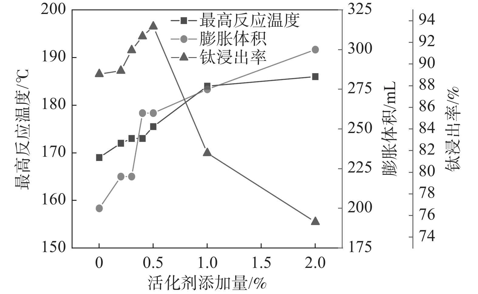
固定反应酸矿比为1.56∶1,反应酸浓度为80%,考察活化剂添加量对酸浸过程最高反应温度、膨胀体积以及钛浸出率的影响,结果如图3所示。
 图 3 活化剂添加量对最高反应温度、钛浸出率及膨胀体积的影响Figure 3. Effect of activator addition on the maximum reaction temperature, Ti leaching rate and expansion volume
从图3可以看出,随着活化剂加量增加,最高反应温度和膨胀体积逐渐增加。由于该活化剂与硫酸反应为放热反应,并在高温下分解产生气体,在活化剂加量较低(<0.4%)时,产生的总热量和气体较少,所以导致体系反应温度和膨胀体积的增加并不显著,随着加量的进一步提升,反应放出大量的热和气体,体系的反应温度和膨胀体积显著增加。但是,添加量达到1%以后,最高反应温度不再继续升高,而膨胀体积仍持续上升,这是因为当加量较高时,气体带走了部分热量,导致体系反应温度不再升高。活化剂加量为0.5%时,钛浸出率达到最高值93.47%,此时,酸浸反应最高温度达到176 ℃,膨胀体积达到260 mL。表明适应的体积膨胀有助于钛精矿酸浸过程中的传热、传质及水分挥发,维持体系较高的反应温度和速率。
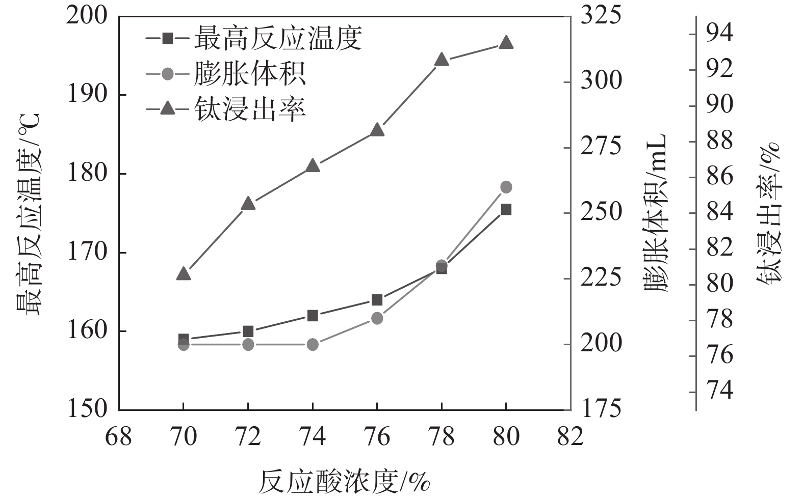
固定反应酸矿比为1.56∶1,熟化温度为140 ℃,熟化2.5 h,考察活化剂添加量为0.5%时,反应酸浓度对酸浸过程最高反应温度、膨胀体积以及浸出率的影响,结果如图4所示。从图4的结果可以看出,反应酸浓度为70%和80%时的最高温度分别为159 ℃和175.5 ℃,与表1中未加活化剂相比,活化剂的加入显著提高了反应最高温度。这是由于活化剂与硫酸反应放出大量的热,会提高反应体系温度,从而增强低浓度下钛浸出率[16]。
 图 4 反应酸浓度对最高反应温度、膨胀体积及钛浸出率的影响Figure 4. Effect of acid concentration on the maximum reaction temperature, expansion volume and Ti leaching rate
2.3 活化剂强化酸浸反应机制探讨
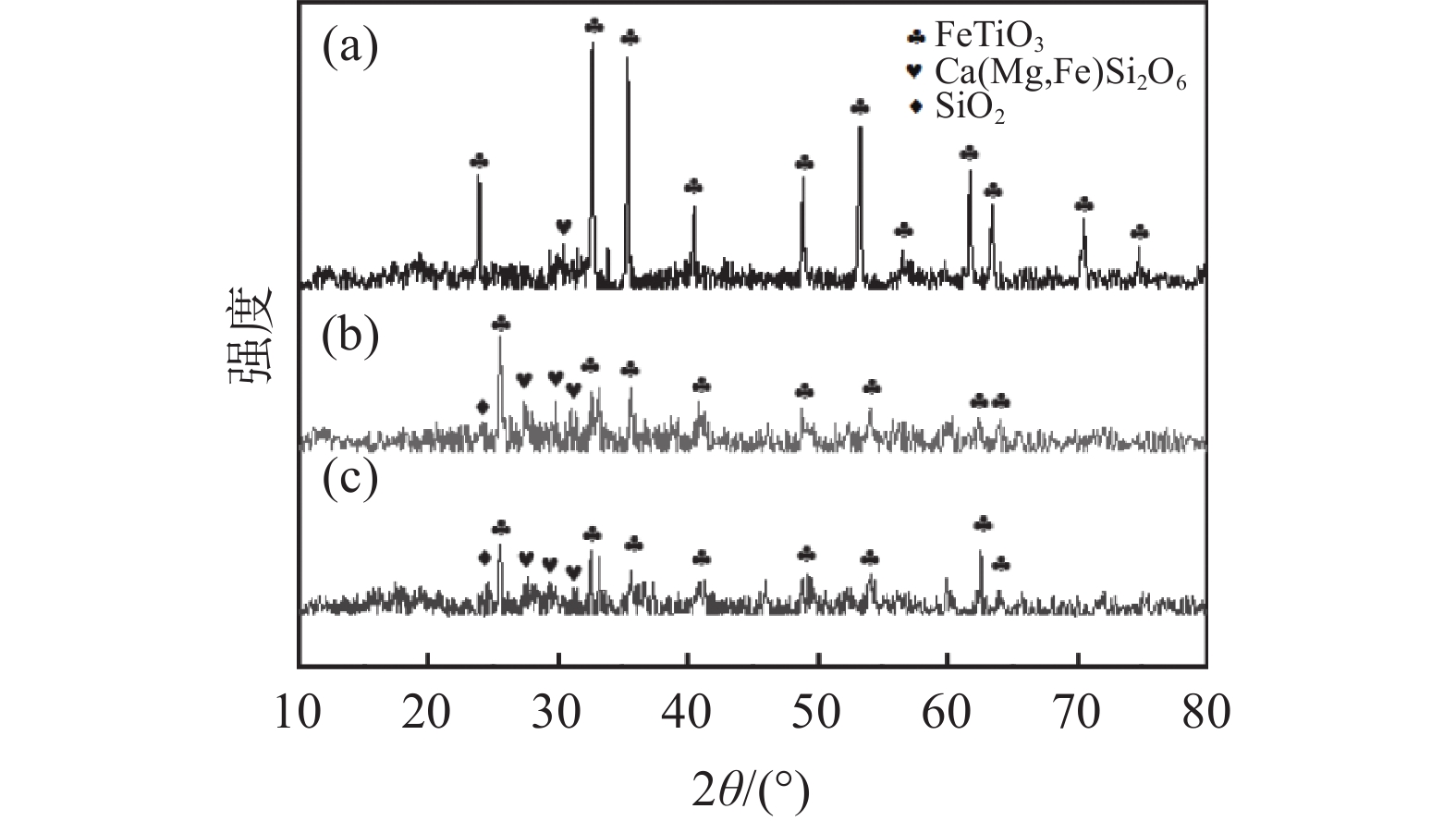
为了探讨活化剂对钛精矿酸浸的影响机制,对钛精矿以及酸浸残渣进行化学成分、物相分析、微观形貌及能谱分析。图5(a)的XRD分析结果表明,钛精矿的主要衍射峰对应FeTiO3六方晶体结构的标准谱图(JCPDS No. 29-0733),以及少量非晶态的硅酸盐相,FeTiO3衍射峰比较尖锐,强度高,表明钛精矿为高度结晶。图5(b)(c)酸浸后残渣的XRD谱图中FeTiO3的特征衍射峰强度明显降低。加入活化剂酸浸残渣(图5(c))中FeTiO3的衍射峰强度比未加活化剂酸浸残渣的衍射峰强度低,表明活化剂有助于减少残渣中FeTiO3物相的含量。从表3酸浸残渣的化学组成分析结果可知,加入活化剂酸浸残渣中的Fe2O3和TiO2含量显著降低,而SiO2和CaO的含量分别从1.75%和1.09%提高至3.69%和2.85%。这是因为活化剂的加入强化了硫酸对钛精矿物相的破坏,提高了钛精矿中铁和钛的溶出率,而辉石、长石等硅酸盐相酸溶性相对钛铁矿酸溶性差,减少幅度少,此外硅酸盐酸浸后产物主要以硅酸形式存在,其吸附性较强,随残渣走,从而使浸出残渣的硅和钙组分得到了富集,导致其含量上升[17]。
 图 5 钛精矿和酸浸残渣的XRD谱(a)钛精矿;(b)未加活化剂酸浸残渣;(c)加活化剂酸浸残渣Figure 5. XRD patterns of titanium concentrate and acid leaching residue表 3 酸浸残渣成分分析Table 3. Compositions of acid hydrolysis residue
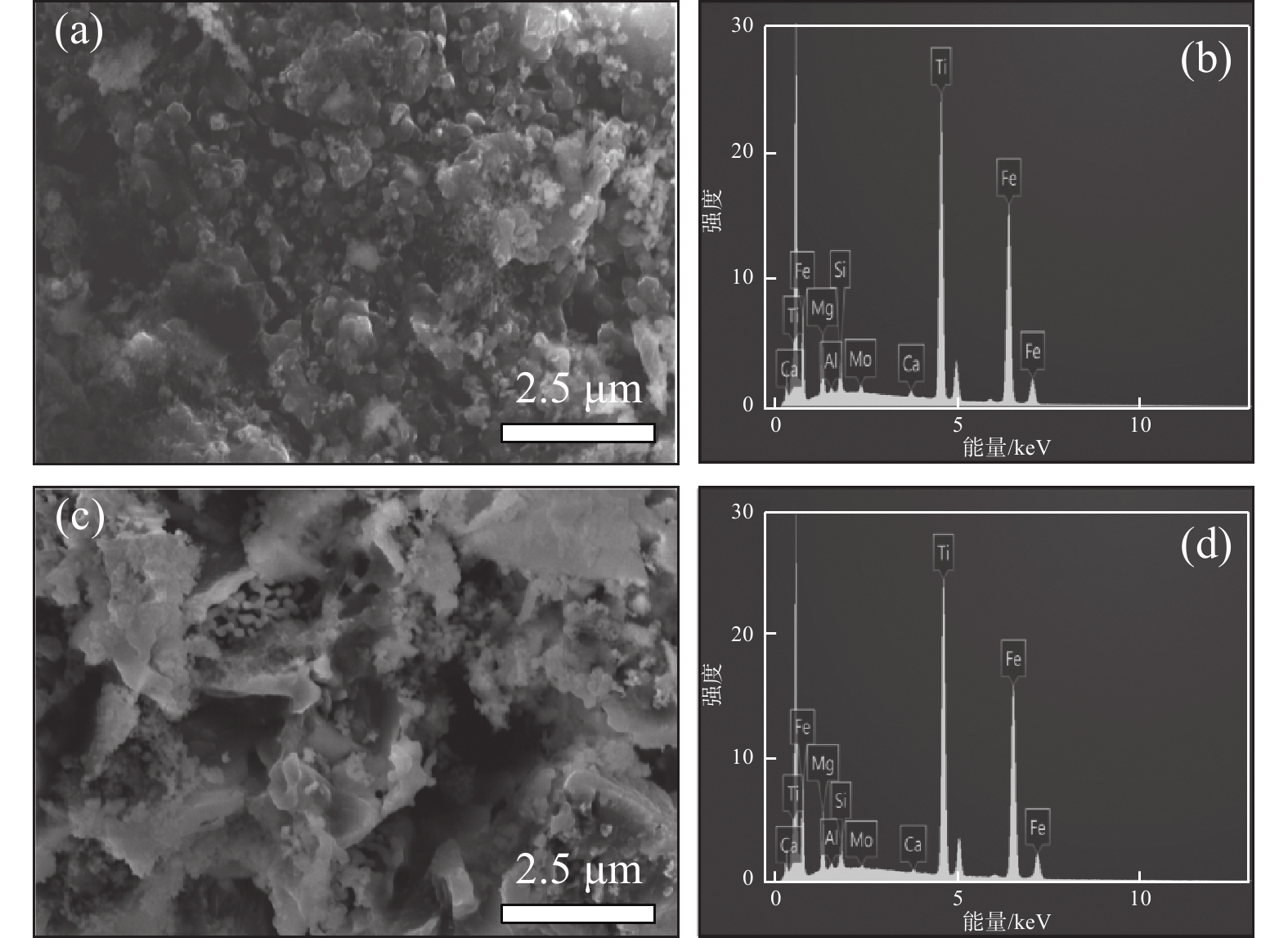
% 成分 SiO2 Fe2O3 MgO S TiO2 CaO MnO Cr2O3 未加活化剂 1.75 20.77 0.72 4.65 31.61 1.09 0.32 0.67 活化剂加量0.5% 3.69 12.31 0.44 6.41 21.70 2.85 0.10 0.07 从图6酸浸残渣的SEM图片可知,图6(a)中未加活化剂酸浸残渣比较致密,而图6(c)中加入活化剂的酸浸残渣呈疏松的多孔状。这种多孔结构有利于硫酸扩散到钛精矿颗粒内层进行酸浸反应,也有利于浸出过程中反应后的物质溶解析出,提高钛浸出率。从残渣的EDS能谱看出,加入活化剂酸浸残渣中的铁和钛元素特征峰强度(图6(d))比未添加活化剂所得浸残渣中的铁和钛元素特征峰强度(图6(b))更低,表明其含量更低。进一步验证了活化剂使钛精矿中更多的铁和钛进入到了液相中,进一步证实了活化剂对钛浸出率有促进作用。
 图 6 酸浸残渣SEM和EDS分析(a)(b) 未加活化剂酸浸残渣;(c)(d)加活化剂酸浸残渣Figure 6. SEM and EDS analysis of acid leaching residue
3. 结论
1) 对硫酸法钛白生产过程中的酸平衡进行理论分析,在当前废酸浓缩浓度为50%时,实现酸平衡的反应酸浓度值为80%。
2) 分析了影响钛精矿在低酸浓度下浸出率低的原因,主要是反应热效应差,导致反应温度低,钛浸出率低。
3) 活化剂的加入,一方面可以提高酸浸反应最高温度,另一方面高温下热分解产生的气体可以改善固相物表面结构,增加疏松度,提高浸出效果。在添加量为0.5%时,在反应酸浓度80%, 140 ℃下熟化2.5 h,浸出率达到最高值93.47%,而未添加活化剂的酸解浸出率仅为89.08%。
-
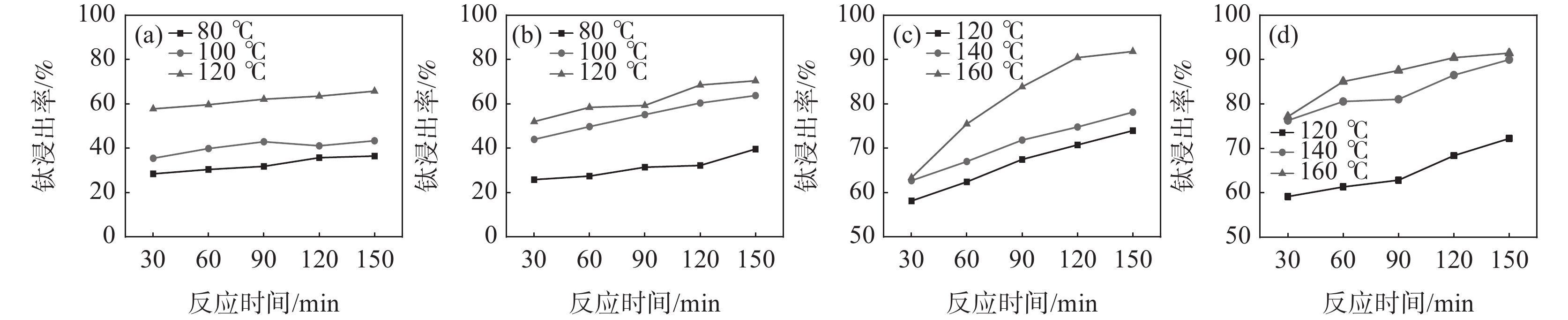
图 1 不同反应酸浓度下的钛浸出率
Figure 1. Effect of acid concentration on Ti leaching rate
(a)50%;(b)60%;(c)70%;(d)80%
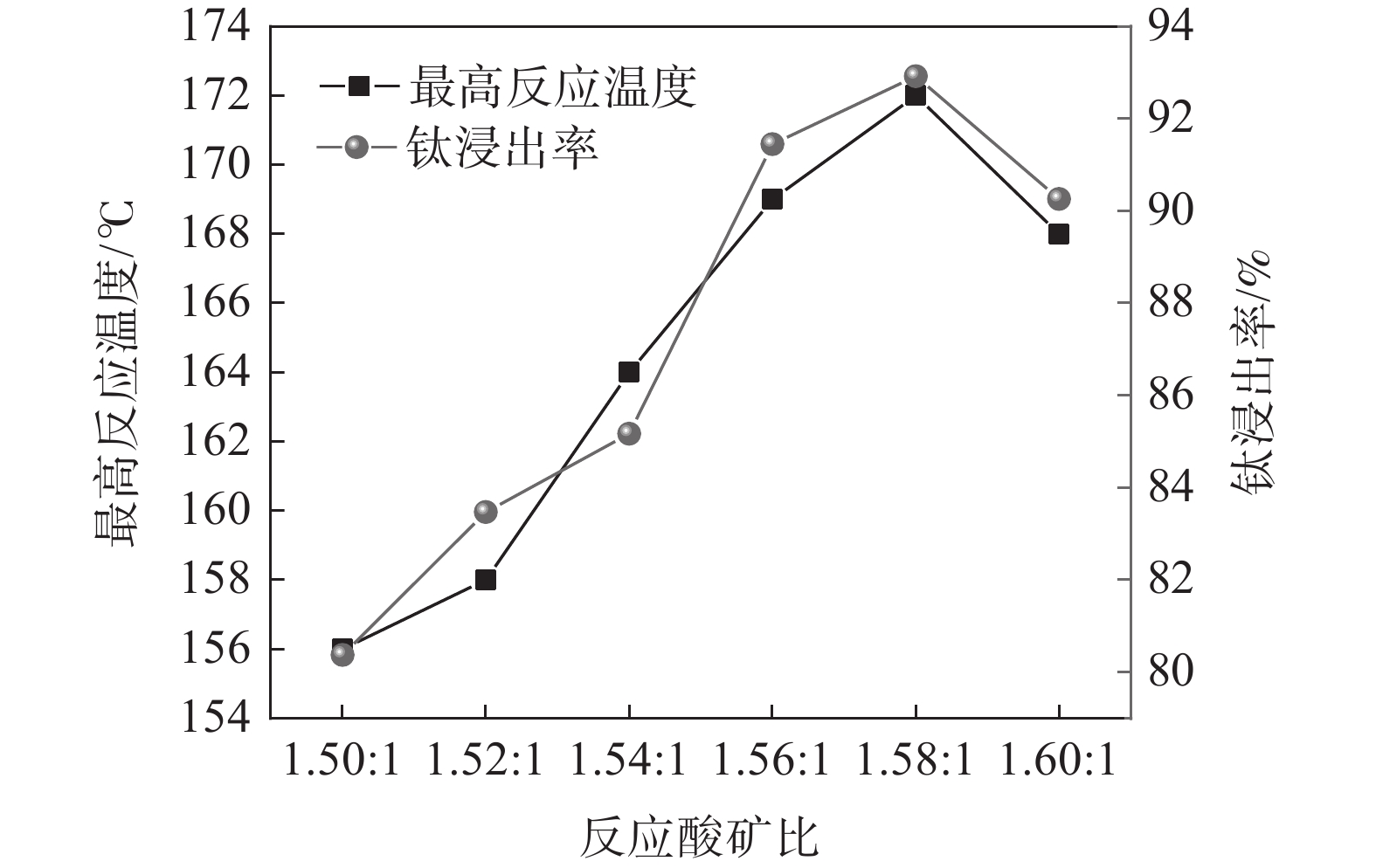
图 2 酸矿比对最高反应温度和Ti浸出率的影响
Figure 2. Effect of acid-to-ore ratio on the maximum reaction temperature and Ti leaching rate

图 3 活化剂添加量对最高反应温度、钛浸出率及膨胀体积的影响
Figure 3. Effect of activator addition on the maximum reaction temperature, Ti leaching rate and expansion volume

图 4 反应酸浓度对最高反应温度、膨胀体积及钛浸出率的影响
Figure 4. Effect of acid concentration on the maximum reaction temperature, expansion volume and Ti leaching rate

图 5 钛精矿和酸浸残渣的XRD谱
(a)钛精矿;(b)未加活化剂酸浸残渣;(c)加活化剂酸浸残渣
Figure 5. XRD patterns of titanium concentrate and acid leaching residue

图 6 酸浸残渣SEM和EDS分析
(a)(b) 未加活化剂酸浸残渣;(c)(d)加活化剂酸浸残渣
Figure 6. SEM and EDS analysis of acid leaching residue
表 1 不同废酸浓度下酸平衡时的反应酸浓度
Table 1. Reaction acid concentrations at acid equilibrium under different wasts acid concentration
酸矿比 不同废酸浓度(%)下反应酸浓度/% 20 30 40 45 50 55 60 1.52 47.32 60.40 70.09 74.0 77.56 80.68 83.48 1.53 47.48 60.56 70.22 74.17 77.66 80.77 83.56 1.54 47.64 60.71 70.35 74.29 77.77 80.86 83.64 1.55 47.80 60.86 70.48 74.40 77.87 80.96 83.72 1.56 47.96 61.00 70.61 74.52 77.97 81.05 83.80  下载: 导出CSV
表 2 不同反应酸浓度下酸浸反应参数
Table 2. Acid leaching reaction parameters under different reaction acid concentrations
反应酸浓度/% 沸点/ ℃ 最高反应温度/ ℃ 50 124 119 60 141.8 128 70 162.2 138 80 200 169 84 221.3 179
下载: 导出CSV
表 3 酸浸残渣成分分析
Table 3. Compositions of acid hydrolysis residue
% 成分 SiO2 Fe2O3 MgO S TiO2 CaO MnO Cr2O3 未加活化剂 1.75 20.77 0.72 4.65 31.61 1.09 0.32 0.67 活化剂加量0.5% 3.69 12.31 0.44 6.41 21.70 2.85 0.10 0.07
下载: 导出CSV
-
[1] Bi Sheng. Status, future and development of China’s titanium dioxide industry in 2023[J]. Iron Steel Vanadium Titanium, 2024,45(1):1-3. (毕胜. 2023年中国钛白粉行业的现状、未来及发展[J]. 钢铁钒钛, 2024,45(1):1-3. doi: 10.7513/j.issn.1004-7638.2024.01.001Bi Sheng. Status, future and development of China’s titanium dioxide industry in 2023[J]. Iron Steel Vanadium Titanium, 2024, 45(1): 1-3. doi: 10.7513/j.issn.1004-7638.2024.01.001 [2] Wang Haibo, Sun Ke. Study on concentration process of titanium white waste acid by sulfuric acid method[J]. Iron Steel Vanadium Titanium, 2023,44(5):116-121. (王海波, 孙科. 硫酸法钛白废酸浓缩工艺研究[J]. 钢铁钒钛, 2023,44(5):116-121. doi: 10.7513/j.issn.1004-7638.2023.05.018Wang Haibo, Sun Ke. Study on concentration process of titanium white waste acid by sulfuric acid method[J]. Iron Steel Vanadium Titanium, 2023, 44(5): 116-121. doi: 10.7513/j.issn.1004-7638.2023.05.018 [3] Xu Bowen, Zhang Tao, Li Lv, et al. Analysis of the composition and formation mechanism of fouling in the concentration process of titanium white waste acid[J]. Industrial & Engineering Chemistry Research, 2023,62(23):9325-9334. [4] Wang Haibo, Wang Kui, Sun Ke, et al. Cause analysis of blockage in heat exchanger of titanium white waste acid concentration by sulfuric acid method[J]. Iron Steel Vanadium Titanium, 2021,42(5):115-119. (王海波, 王奎, 孙科, 等. 硫酸法钛白废酸浓缩换热器堵塞成因分析[J]. 钢铁钒钛, 2021,42(5):115-119. doi: 10.7513/j.issn.1004-7638.2021.05.018Wang Haibo, Wang Kui, Sun Ke, et al. Cause analysis of blockage in heat exchanger of titanium white waste acid concentration by sulfuric acid method[J]. Iron Steel Vanadium Titanium, 2021, 42(5): 115-119. doi: 10.7513/j.issn.1004-7638.2021.05.018 [5] Wang Minghua, Du Xinghong, Sui Zhitong. Kinetics of acidolysis of rich titanium concentrate by H2SO4[J]. The Chinese Journal of Nonferrous Metals, 2001,11(1):131-134. (王明华, 都兴红, 隋智通. H2SO4分解富钛精矿的反应动力学[J]. 中国有色金属学报, 2001,11(1):131-134. doi: 10.3321/j.issn:1004-0609.2001.01.029Wang Minghua, Du Xinghong, Sui Zhitong. Kinetics of acidolysis of rich titanium concentrate by H2SO4[J]. The Chinese Journal of Nonferrous Metals, 2001, 11(1): 131-134. doi: 10.3321/j.issn:1004-0609.2001.01.029 [6] Maciej Jabłoński, Sandra Tylutka. The influence of initial concentration of sulfuric acid on the degree of leaching of the main elements of ilmenite raw materials[J]. J. Therm Anal Calorim, 2015, 124:355-361. [7] Du Jun, Li Chun, Yuan Shaojun, et al. A coupling process of mechanical activation and acid digestion of ilmenite[J]. Chemical Reaction Engineering and Technology, 2014,30(4):321-328. (杜均, 李春, 袁绍军, 等. 钛铁矿机械活化-稀酸酸解反应耦合[J]. 化学反应工程与工艺, 2014,30(4):321-328.Du Jun, Li Chun, Yuan Shaojun, et al. A coupling process of mechanical activation and acid digestion of ilmenite[J]. Chemical Reaction Engineering and Technology, 2014, 30(4): 321-328. [8] Wang Xiaomei, Li Chun,Yue Hairong, et al. Effects of mechanical activation on the digestion of ilmenite in dilute H2SO4[J]. Chinese Journal of Chemical Engineering, 2019,27:575-586. doi: 10.1016/j.cjche.2018.06.020 [9] Wu Jianchun, Lu Ruifang, Shi Ruicheng. Study on the acidolysis properties of titanium ore recovered from acidolysis residue[J]. Iron Steel Vanadium Titanium, 2021,42(3):37-43. (吴健春, 路瑞芳, 石瑞成. 酸解残渣回收矿的酸解性能研究[J]. 钢铁钒钛, 2021,42(3):37-43. doi: 10.7513/j.issn.1004-7638.2021.03.006Wu Jianchun, Lu Ruifang, Shi Ruicheng. Study on the acidolysis properties of titanium ore recovered from acidolysis residue[J]. Iron Steel Vanadium Titanium, 2021, 42(3): 37-43. doi: 10.7513/j.issn.1004-7638.2021.03.006 [10] Nayl A A, Awwad N S, AlyH F. Kinetics of acid leaching of ilmenite decomposed by KOH Part 2. Leaching by H2SO4 and C2H2O4[J]. Journal of Hazardous Materials, 2009,168:793-799. doi: 10.1016/j.jhazmat.2009.02.076 [11] Liu Qingsheng, Tu Tao, Guo Hao, et al. Complexation extraction of scheelite and transformation behavior of tungsten-containing phase using H2SO4 solution with H2C2O4 as complexing agent[J]. Trans. Nonferrous Met. Soc. China, 2021, 31: 3150-3161. [12] Wu Aixiang, Ai Chunming, Wang Yiming, et al. Influence of surfactant on permeability of heap leaching of copper ore[J]. Journal of Central South University (Science and Technology), 2014,45(3):895-901. (吴爱祥, 艾纯明, 王贻明, 等. 表面活性剂对铜矿石堆浸渗透性的影响[J]. 中南大学学报(自然科学版), 2014,45(3):895-901.Wu Aixiang, Ai Chunming, Wang Yiming, et al. Influence of surfactant on permeability of heap leaching of copper ore[J]. Journal of Central South University (Science and Technology), 2014, 45(3): 895-901. [13] Tian Hong, Ma Mengyu, Ye Hengpeng, et al. Leaching of manganese from low-grade manganese ore using sulfuric acid with synthesized atmospheric surfactant[J]. Hydrometallurgy of China, 2021, 40(4): 272-277. (田鸿, 马梦雨, 叶恒朋, 等. 用两性表面活性剂辅助浸出低品位锰矿石中的锰[J]. 湿法冶金, 2021, 40(4): 272-277.Tian Hong, Ma Mengyu, Ye Hengpeng, et al. Leaching of manganese from low-grade manganese ore using sulfuric acid with synthesized atmospheric surfactant[J]. Hydrometallurgy of China, 2021, 40(4): 272-277. [14] YB/T 159.1-2015. Titanium concentrate (rock minerals)- Determination of titanium dioxide content- The ferric ammonium sulfate titrimetric method[S]. Beijin: Metallurgical industry press, 2015. (YB/T 159.1-2015 .钛精矿(岩矿)二氧化钛含量的测定 硫酸铁铵滴定法[S]. 北京: 冶金工业出版社, 2015.YB/T 159.1-2015. Titanium concentrate (rock minerals)- Determination of titanium dioxide content- The ferric ammonium sulfate titrimetric method[S]. Beijin: Metallurgical industry press, 2015. [15] Ma Weiping. Research on acidolysis of Panxin titanium concentrate with sulfuric acid[J]. Inorganic Chemicals Industry, 2013,45(5):24-26. (马维平. 硫酸酸解攀西钛精矿技术研究[J]. 无机盐工业, 2013,45(5):24-26. doi: 10.3969/j.issn.1006-4990.2013.05.008Ma Weiping. Research on acidolysis of Panxin titanium concentrate with sulfuric acid[J]. Inorganic Chemicals Industry, 2013, 45(5): 24-26. doi: 10.3969/j.issn.1006-4990.2013.05.008 [16] Maciej Jabłoński, Sandra Tylutka. The influence of initial concentration of sulfuric acid on the degree of leaching of the main elements of ilmenite raw materials[J]. J Therm Anal Calorim, 2016,124:355-361. doi: 10.1007/s10973-015-5114-y [17] Wang Haibo, Wu Xiaoping, Gao Jian, et al. Kinetics of sulfuric acid leaching of ilmenite[J]. Iron Steel Vanadium Titanium, 2020,41(6):6-10. (王海波, 吴小平, 高健, 等. 硫酸浸取钛铁矿动力学研究[J]. 钢铁钒钛, 2020,41(6):6-10. doi: 10.7513/j.issn.1004-7638.2020.06.002Wang Haibo, Wu Xiaoping, Gao Jian, et al. Kinetics of sulfuric acid leaching of ilmenite[J]. Iron Steel Vanadium Titanium, 2020, 41(6): 6-10. doi: 10.7513/j.issn.1004-7638.2020.06.002 -

 下载:
下载:


 点击查看大图
计量
- 文章访问数: 115
- HTML全文浏览量: 35
- PDF下载量: 12
- 被引次数: 0

